Pinout assignments 66, Appendix, Ba d c – Hatteland Display 13 inch - HD 13T21 MMC (Widescreen, Inte Cor2 Duo CPU) User Manual
Page 66
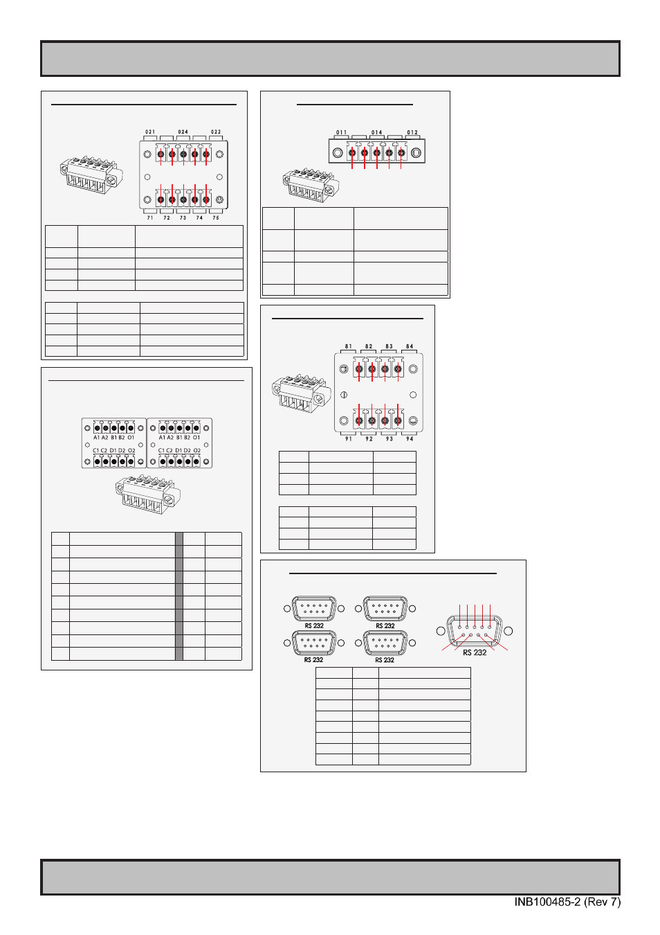
Pinout Assignments
66
IND100241-24
Appendix
5-pin Digital Output Module
“Safety Signal Relay”
X1
DIG
OUT
1 2 3 4 5
PIN 01 X1 - Out:
011 COM (Common
Center Terminal)
PIN 02 X1 - N/C
Not Connected
Not in use
PIN 03 X1 - Out:
014 NO (Normally Open)
PIN 04 X1 - N/C
Not Connected
Not in use
PIN 05 X1 - Out:
012 NC (Normally Closed)
10-pin Digital Output / Input & Serial Module
“Mechanical Relay & COM (isolated RS-422/485)”
X1
DIG
OUT
X7
SER
I/O
1 2 3 4 5
1 2 3 4 5
PIN 01 X1 - Out:
021 COM (Common Center
Terminal)
PIN 02 X1 - N/C
Not Connected / Not used
PIN 03 X1 - Out:
024 NO (Normally Open)
PIN 04 X1 - N/C
Not Connected / Not used
PIN 05 X1 - Out:
022 NC (Normally Closed)
PIN 01 X7 - In:
71
Rx+ (Receive Data +)
PIN 02 X7 - In:
72
Rx- (Receive Data -)
PIN 03 X7 - Out:
73
Tx+ (Transmit Data +)
PIN 04 X7 - Out:
74
Tx- (Transmit Data -)
PIN 05 X7 - GND:
75 SGnd (Signal Ground)
4+4 pin CAN I/O Module, 2 channels
Type Number “HT 00254 OPT-A1”
X8
CAN1
X9
CAN2
1 2 3 4
1 2 3 4
Pin 01 X8 - Can1:
081 In Low
Pin 02 X8 - Can1:
082 Out Low
Pin 03 X8 - Can1:
083 In High
Pin 04 X8 - Can1:
084 Out High
Pin 01 X9 - Can2:
091 In Low
Pin 02 X9 - Can2:
092 Out Low
Pin 03 X9 - Can2:
093 In High
Pin 04 X9 - Can2:
094 Out High
10+10 pin Isolated Digital Input/Output Module
Type Number “HT00268 OPT-A1”
Module A Module B
Module A Module B
A1 External Power +
A1
IN+[0]
A2 N/C (Not Connected)
A2
IN-[0]
B1 External Power - (GND1)
B1
IN+[1]
B2 N/C (Not Connected)
B2
IN-[1]
O1 HS[0]
O1 N/C
C1 HS[1]
C1 IN+[2]
C2 N/C (Not Connected)
C2 IN-[2]
D1 HS[2]
D1 IN+[3]
D2 N/C (Not Connected)
D2 IN-[3]
O2 HS[3]
O2 N/C
COM Module RS-232 - 4 x ports, 9-pin DSUB Male
Type Number “PCA100294-1”
B
A
D
C
1 2 3 4 5
6 7
8 9
PIN 01 DCD Data Carrier Detect
PIN 02 RxD Receive Data
PIN 03 TxD Transmit Data
PIN 04 DTR Data Terminal Ready
PIN 05 GND Signal Ground
PIN 06 DSR Data Set Ready
PIN 07 RTS Request To Send
PIN 08 CTS Clear To Send
PIN 09 RI
Ring Indicator