Appendix pinout assignments – Hatteland Display 13 inch - HD 13T21 MMC (Widescreen, Inte Cor2 Duo CPU) User Manual
Page 65
65
IND100241-24
Appendix
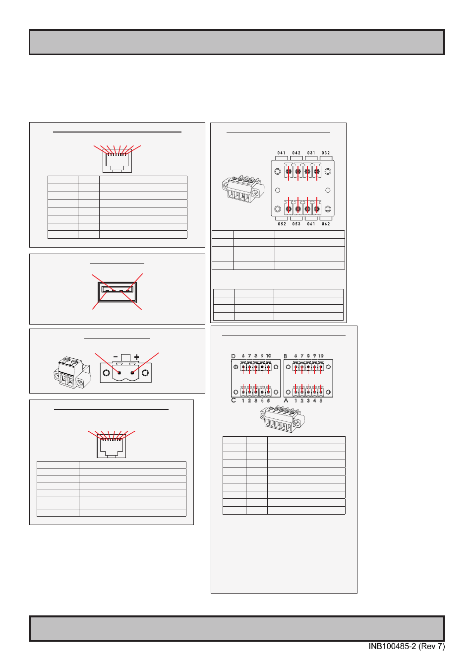
Pinout Assignments
8-pin RJ45 10/100/1000Mbps LAN/Ethernet
1 2 3 4 5 6 7 8
PIN 01 D0P+ Differential Pair 0 (Positive)
PIN 02 D0N- Differential Pair 0 (Negative)
PIN 03 D1P+ Differential Pair 1 (Positive)
PIN 04 D2P+ Differential Pair 2 (Positive)
PIN 05 D2N- Differential Pair 2 (Negative)
PIN 06 D1N- Differential Pair 1 (Negative)
PIN 07 D3P+ Differential Pair 3 (Positive)
PIN 08 D3N- Differential Pair 3 (Negative)
Connectors illustrated here are either standard by factory default or may be available (through factory customization).
Note that some combinations may not be possible due to space restrictions. List also valid for customized models. All
pin out assignments are seen from users Point of View (POV) while looking straight at the connector. Please review
the dedicated datasheet or technical drawings for your actual unit to identify and determine the presence of desired
connector. Detailed information about Housing Connectors (terminal blocks) can be found earlier in this manual.
4-pin USB TYPE A
Pin 2: Negative Data
Pin 1: VCC +5V
Pin 3: Positive Data
Pin 4: Ground
2-pin DC Power Input,
Pin 2: Negative -
Pin 1: Positive +
8-pin Digital Output / Input Module
“Solid State Relay”
X1
DIG
OUT
X1
DIG
IN
1 2 3 4
1 2 3 4
Pin 01 X1 - Out:
041 Out +
Pin 02 X1 - Out:
042 Out -
Pin 03 X1 - Out:
031 COM (Common Center
Terminal) *
Pin 04 X1 - Out:
032 NO (Normally Open)*
* IEC 60950 Compliant, 48VDC
Pin 01 X1 - In:
052 +24VDC
Pin 02 X1 - In:
053 GND (Ground)
Pin 03 X1 - In:
061 +24VDC
Pin 04 X1 - In:
062 +Input
10+10 pin RS-422 / RS-485 NMEA Module
Type Number “PCA100293-1”
6 7 8 9 10
1 2 3 4 5
6 7 8 9 10
1 2 3 4 5
PIN 01 TxD- Transmit Data Negative
PIN 02 TxD+ Transmit Data Positive
PIN 03 GND Isolated Ground
PIN 04 RxD- Receive Data Negative
PIN 05 RxD+ Receive Data Positive
PIN 06 TxD- Transmit Data Negative
PIN 07 TxD+ Transmit Data Positive
PIN 08 GND Isolated Ground
PIN 09 RxD- Receive Data Negative
PIN 10 RxD+ Receive Data Positive
RS-485 Half Duplex (2-wire) Confi guration:
Connect TX and RX pair-wise:
TX- to RX-, TX+ to RX+.
*Note: The jumper for “force of transmitter” is
open by factory default. For some custom
models this jumper is preset to closed (active),
in that case unit has to be opened and jumper
set to open to allow Half Duplex mode.
8-pin RJ-45 10/100Mbps LAN/Ethernet
PCA100298-1 / HT 00274 OPT-A1
1 2 3 4 5 6 7 8
Pin 01 - TDP Transmit Differential Pair (Positive)
Pin 02 - TDN Transmit Differential Pair (Negative)
Pin 03 - RDP Receive Differential Pair (Positive)
Pin 04 - NC
Not Connected
Pin 05 - NC
Not Connected
Pin 06 - RDN Receive Differential Pair (Negative)
Pin 07 - NC
Not Connected
Pin 08 - NC
Not Connected