Data sheet, Specifications - can module with co-processor, 1 x can, 2 channels, can module with co-processor – Hatteland Display 13 inch - HD 13T21 MMC (Widescreen, Inte Cor2 Duo CPU) User Manual
Page 39
39
IND100129-134
All specifications are subject to change without prior notice!
HT 00254 OPT-A1
Specifications - CAN Module with CO-Processor
1/2
This information may not, in whole or in part, be copied, photocopied,
reproduced, translated or reduced to any electronic medium or machine-
readable form without the prior written consent of Hatteland Display AS.
The products may not be copied or duplicated in any way.
Dimensions might be shown with or without decimals and indicated as mm [inches]. Tolerance on drawings is +/- 1mm. For accurate measurements, check relevant DWG fi le.
DATA SHEET
Hatteland Display AS, Åmsosen, N-5578 Nedre Vats, Norway
Tel: (+47) 4814 2200 - [email protected] - www.hatteland-display.com
1 x CAN, 2 channels, CAN Module with CO-Processor
Manufacturer:
Hatteland Display AS
Product:
CAN Module with CO-Processor
Typenumber:
HT 00254 OPT-A1
Last Revised:
31 Oct 2014
Revision#:
14
CAN Module with CO-Processor (NXP LPC1756) is a USB to dual isolated CAN interface board. This card will mainly be integrated,
electrical and mechanical by factory default for Series X 8, 12, 13, 15, 17, 19, 24, 26 inch Panel Computers and selected Stand-alone
Computers. The Hatteland Display CAN Module is delivered with software download functions and standard API, SAE J2534, which allow
the user to add their own functions, such as real time critical functions, and high level CAN protocol. The CAN Module can operate as
a standalone unit, which can be configured to operate independent of application software and hardware. This allow the user to use
the CAN Module for time and safe critical operations.
Cost effective CAN solution, Withstand marine requirements, General and open architecture that will allow the end customer to modify
and handle the source code, General CAN interface support, NMEA2000, J1939, CANOpen.
Description:
Specifications
• Number of CAN interfaces 2 independent channels isolated from each other
• Version
CAN 2.0B
• Isolation
Galvanic isolation 2kV, CAN1 to CAN2 and port to chassis
• Protection
- Continuous short circuit signal to signal
- Continuous short circuit to isolated GND
- Continuous shorts to ±27V
• ESD rating on CAN bus
ESD rating of ±12kV Human body model
• Min Baud rate
64kbit
• Max baud rate
500kbit
• Address mode
11/29bit
• Terminating
No termination on PCB, user will put them in connector
• PCB Connector
Weidmüller 1973600000 (SCD 3.81/08/90F 3.2SN BK BX) (Do not connect to this, use Terminal Block)
• Cable connector
2 x Weidmüller 1792970000 (BCZ 3.81/04/180F SN BK BX) Terminal Block (see illustration below)
• Cable
Twisted pair, no ground
• Supported protocols
SAE J2934 Standard Data Bus Interface
• Supported OS
Embedded Enterprise (WEE): Microsoft® Windows® XP Professional (Eng, SP3, SP2c),
Microsoft® Windows® Server 2003/2008/2008R2 (Eng), Microsoft® Windows® 2003/2008/2008R2
(Eng), Microsoft® Windows® 7 Professional/Ultimate (Eng, SP1).
Linux: openSUSE® 11.4, Fedora™ 15, Ubuntu® 10.04 LTS, Ubuntu® 12.04 LTS.
Note: Listed Operating Systems above are hardware/platform dependent. Please check datasheet for speci c unit if OS is supported.
• Test and certi cate
Hatteland Display standard (tested / type approved by the following classification societies):
IEC 60945 4th (EN 60945:2002), IACS E10, ClassNK - Nippon Kaiji Kyokai,
GL - Germanischer Lloyd, DNV - Det Norske Veritas, ABS - American Bureau of Shipping,
CCS - China Classification Society (Pending), BV - Bureau Veritas,
LRS - Lloyd’s Register of Shipping (Pending), EU RO MR - Mutual Recognition
• Relevant Documentation
http://www.hatteland-display.com/pdf/misc/doc101357-1_hd_can_module_programmer_guide_windows.pdf
http://www.hatteland-display.com/pdf/misc/doc101356-1_hd_can_module_programmer_guide_linux.pdf
http://www.hatteland-display.com/drivers/can_gw_application_note_package.zip
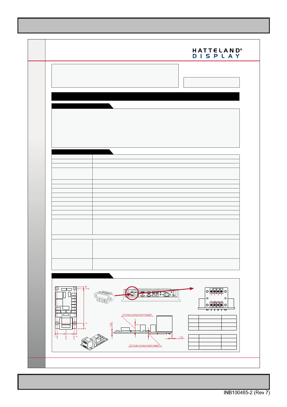
Note: Product below for illustration only. Location of module and product size/design may differ. Connector/pinning remain the same.
Illustration and Pinning:
X8
CAN1
X9
CAN2
1 2 3 4
1 2 3 4
4-pin Terminal Block 3.81
Pin 01 X8 - Can1:
081 In Low
Pin 02 X8 - Can1:
082 Out Low
Pin 03 X8 - Can1:
083 In High
Pin 04 X8 - Can1:
084 Out High
Pin 01 X9 - Can2:
091 In Low
Pin 02 X9 - Can2:
092 Out Low
Pin 03 X9 - Can2:
093 In High
Pin 04 X9 - Can2:
094 Out High