Functional diagram hi 9910, Front panel – Hanna Instruments HI 9910 User Manual
Page 6
6
FUNCTIONAL DIAGRAM HI 9910
FUNCTIONAL DIAGRAM HI 9910
FUNCTIONAL DIAGRAM HI 9910
FUNCTIONAL DIAGRAM HI 9910
FUNCTIONAL DIAGRAM HI 9910
SINGLE SETPOINT,
SINGLE SETPOINT,
SINGLE SETPOINT,
SINGLE SETPOINT,
SINGLE SETPOINT, pppppH CONTROLLER
H CONTROLLER
H CONTROLLER
H CONTROLLER
H CONTROLLER
pH
0
1
2
ALARM
MTC
ATC
mA OUTPUT
TEMP. COMP.
4/20
0/20
HI 9910
pH
SECONDS
0
90
45
MTC
°C
-10
80
10
0
30
20
60
70
40
50
0
pH
2.0
0.5
1
1.5
COARSE
FINE
SLOPE
OFFSET
PROPORTIONAL SETTINGS
ALARM
ON
OFF
SET
READ
ACID
DOSING
ALK
SET POINT
ALARM DOSING TIME
MINUTES
1
10
2.5
5
7.5
SET pH
ALARM
LINE
1
2
3
4
5
6
7
8
9
10
11
12
14
13
15
16
17
18
19
20
21
22
23
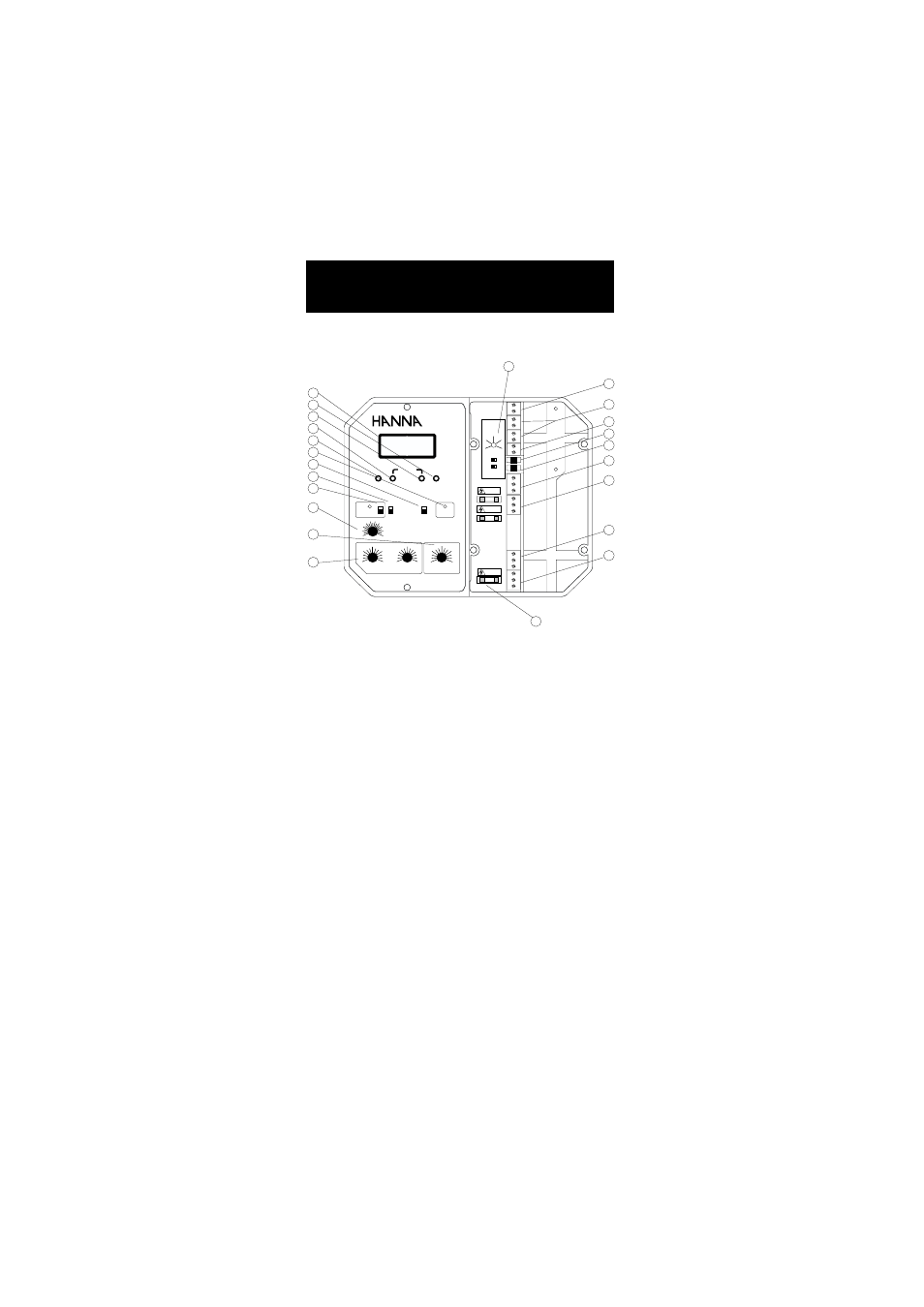
FRONT PANEL
Left panel
1. Liquid Crystal Display
2. Slope calibration trimmer
3. Fine setpoint trimmer
4. Coarse setpoint trimmer
5. Offset calibration trimmer
6. Dosing LED visual signal
7. READ for actual measurement and SET for setpoint
adjustment
8. Acid or Alkaline Dosage selection
9. Alarm LED and switch to disable the alarm
10. Graded dial for Manual Temperature Compensation
11. Overdosage timer
12. Proportional pH band and time cycle settings
Right panel
13. pH alarm setting from 0 to 2 pH
14. Short the terminals if a ground probe is not in use, or
connect the ground probe wire to the Matching Pin terminal
15. Three-wire Pt 100 plus a shield protection