Functional diagram hi 9920, Front panel – Hanna Instruments HI 9910 User Manual
Page 12
12
FUNCTIONAL DIAGRAM HI 9920
FUNCTIONAL DIAGRAM HI 9920
FUNCTIONAL DIAGRAM HI 9920
FUNCTIONAL DIAGRAM HI 9920
FUNCTIONAL DIAGRAM HI 9920
ORP CONTROLLER
ORP CONTROLLER
ORP CONTROLLER
ORP CONTROLLER
ORP CONTROLLER
4/20
0/20
mV
0
100
200
ALARM
mA OUTPUT
0
SECONDS
mV
200
0
TIMER
MINUTES
90
50
45
100
150
COARSE
FINE
CAL
PROPORTIONAL SETTINGS
ALARM
ON
OFF
SET
READ
DOSING
OXID
RED
1
10
2.5
5
7.5
HI 9920
mV
ORP
SET POINT
SET mV
ALARM
LINE
1
3
4
5
6
7
8
9
11
12
14
13
16
18
19
20
21
22
23
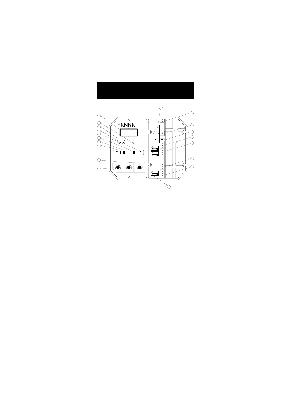
FRONT PANEL
Left panel
1. Liquid Crystal Display
3. Fine setpoint trimmer
4. Coarse setpoint trimmer
5. Calibration trimmer
6. Dosing LED visual signal
7. READ for actual measurement and SET for setpoint
adjustment
8. Oxidization or Reduction Dosage selection
9. Alarm LED and switch to disable the alarm
11. Overdosage timer
12. Proportional ORP band and time cycle settings
Right panel
13. ORP alarm setting from 0 to 200 mV
14. Short the terminals if a ground probe is not in use, or
connect the ground probe wire to the Matching Pin terminal
16. Recorder output contacts
18. 0 to 20 or 4 to 20 mA isolated output switch
19. Triple contact alarm in a normally-closed (NC) or a normally
open (NO) position.