Mechanical layouts – Hanna Instruments HI 9910 User Manual
Page 4
4
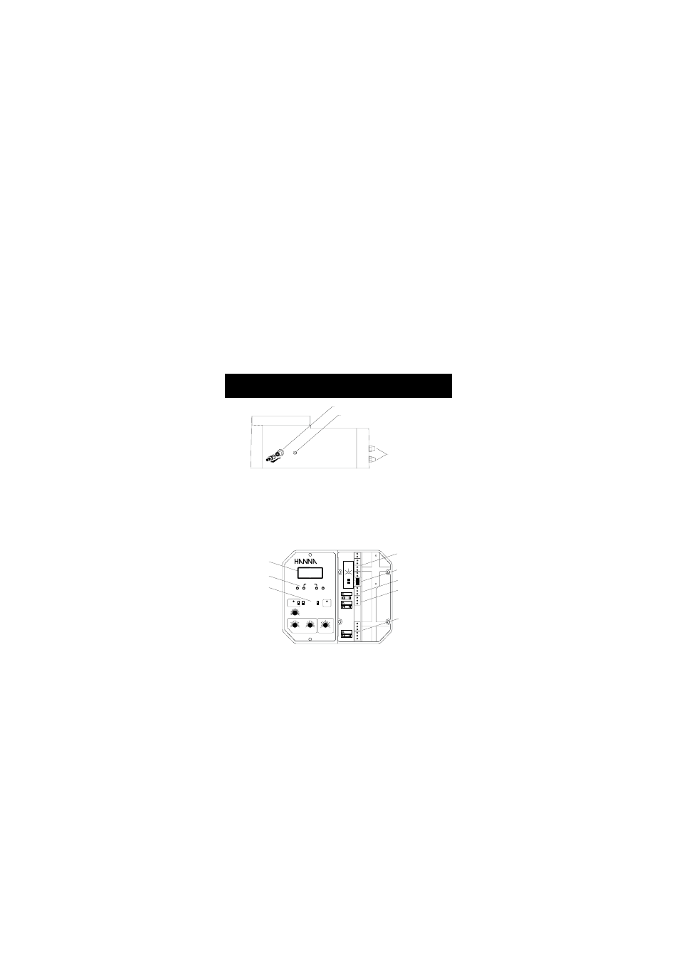
Figure 2 illustrates the controls and terminals on the HI 9910 pH
controller. Layouts vary from model to model based on their features
and capabilities.
MECHANICAL LAYOUTS
MECHANICAL LAYOUTS
MECHANICAL LAYOUTS
MECHANICAL LAYOUTS
MECHANICAL LAYOUTS
BNC CONNECTOR FOR ELECTRODE
WIRING ACCESS
PORTS
4 mm BANANA SOCKET
FOR GROUND PROBE
pH
0
1
2
ALARM
MTC
ATC
mA OUTPUT
TEMP. COMP.
4/20
0/20
HI 9910
pH
SECONDS
0
90
45
MTC
°C
-10
80
10
0
30
20
60
70
40
50
0
pH
2.0
0.5
1
1.5
COARSE
FINE
SLOPE
OFFSET
PROPORTIONAL SETTINGS
ALARM
ON
OFF
SET
READ
ACID
DOSING
ALK
SET POINT
ALARM DOSING TIME
MINUTES
1
10
2.5
5
7.5
SET pH
ALARM
LINE
LCD DISPLAY
CALIBRATION
TRIMMERS
CONTROL KNOBS
AND SWICHES
OUTPUT CONTACTS
TEMP. COMPENSATION
SWITCH
DOSING TERMINALS
POWER SUPPLY
TERMINALS
ALARM CONTACTS
Fig. 2
Fig. 1
Figure 1: displays the connector for electrode and the wiring access
ports.
All models can be wired to work with 110/115V or 220/240V
50/60 Hz power supplies.
The models covered in this manual are:
HI 9910
a single setpoint
pH controller
HI 9911
a dual setpoint
pH controller, specifically designed for
all those applications in which the pH value intends to
oscillate both up and down
HI 9920
ORP controller, designed for numerous industrial
applications, but in particular for swimming pools and
drinking water sanitation