Hanna Instruments HI 9910 User Manual
Page 15
15
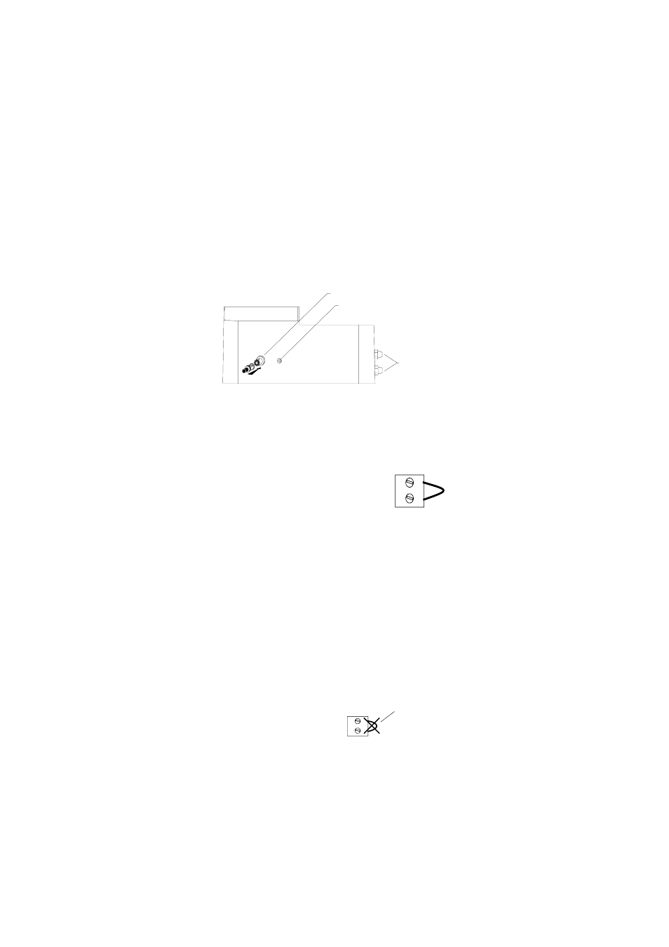
ELECTRODE WITH
BNC CONNECTION
WIRING ACCESS
PORTS
MATCHING PIN FOR GROUND PROBE
•
Before
Before
Before
Before
Before connecting the controller to the mains, wire
connecting the controller to the mains, wire
connecting the controller to the mains, wire
connecting the controller to the mains, wire
connecting the controller to the mains, wire
the controller completely
the controller completely
the controller completely
the controller completely
the controller completely and make all the connections for
pumps, alarm, electrode, set the alarm threshold and adjust the
settings. Upon completion, replace the cover
replace the cover
replace the cover
replace the cover
replace the cover.
Only then
connect the controller to the power supply.
ELECTRODE & GROUND PROBE CONNECTIONS
• Simply attach any combination
pH or ORP electrode with a
male BNC connector (such as HI 1002/3 or HI 2002/3) to the
female BNC socket located on the bottom of the casing and twist
it into a secure position.
• All models provide for a Ground Probe (differential input) to
reduce electrical noise and interference. The
controllers are shipped with the Matching Pin
and Reference terminals shorted (see 14 - Func-
tional Diagram). If you are not using a matching
pin (ground probe), leave the terminals shorted
leave the terminals shorted
leave the terminals shorted
leave the terminals shorted
leave the terminals shorted and skip
the next two paragraphs.
• It is recommended that only electrodes that incorporate a match-
ing pin (such as HI 1003/3 or HI 2003/3) are utilized. In this
case simply attach the 4-mm banana connector of the
attach the 4-mm banana connector of the
attach the 4-mm banana connector of the
attach the 4-mm banana connector of the
attach the 4-mm banana connector of the
matching pin to the socket
matching pin to the socket
matching pin to the socket
matching pin to the socket
matching pin to the socket located next to the BNC
connector on the outer casing (see 25 - Functional Diagram) and
remove the jumper
remove the jumper
remove the jumper
remove the jumper
remove the jumper shorting the matching pin terminals.
• When using a separate probe for grounding purposes, wire it to
the Matching Pin terminal on the right hand panel and remove
remove
remove
remove
remove
the jumper
the jumper
the jumper
the jumper
the jumper (see 14 Functional Diagram).
NOTE:
NEVER leave the jumper in when
using an electrode with a matching
pin. This can shorten the life of the
electrode (reference) drastically.
REMOVE WHEN
USING MATCHING PIN