Conections & wiring, General points – Hanna Instruments HI 9910 User Manual
Page 14
14
CONECTIONS & WIRING
CONECTIONS & WIRING
CONECTIONS & WIRING
CONECTIONS & WIRING
CONECTIONS & WIRING
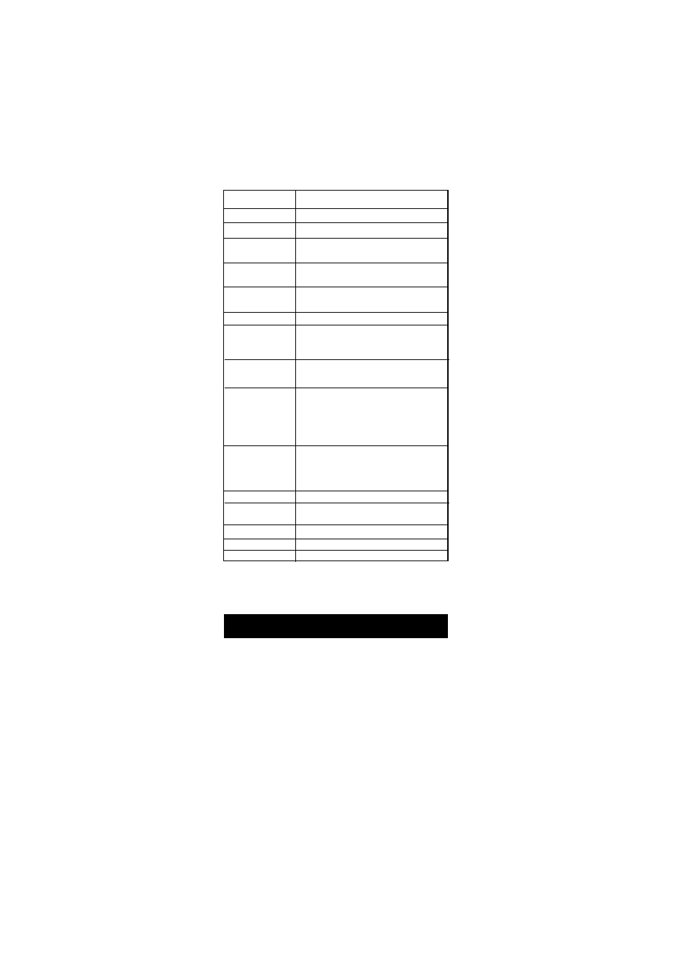
Specifications
HI 9920
RANGE
-500 to 1500 mV
RESOLUTION
1 mV
ACCURACY
± 5 m V
(@20°C/68°F)
TYPICAL EMC
±6 mV
DEVIATION
mA OUTPUT
User-selectable 0 to 20 mA or 4 to 20 mA
over the -500 to 1500 mV range with isolated output
CALIBRATION
Through "CAL" trimmer
SETPOINT
From -500 to 1500 mV with "COARSE" and "FINE"
RANGE 2 trimmers with "OXID" or "RED" selection for oxidizing
or reducing dosage
PROPORTIONAL
ORP setting is adjustable from 0 to 200 mV and
CONTROL
time cycle from 0 to 90 seconds
Normally open or normally closed isolated outputs
(Max. 2A, Max. 240V, resistive load, 1,000,000 strokes).
Terminals are activated when the ORP value varies by
more than the user selectable interval (0 to 200mV)
from setpoint, or due to overdosage
DOSING TERMINALS Relay terminals (115 to 240V, Max.2A,1,000,000
strokes) are activated when mV exceeds the setpoint
with “RED” dosage or when mV falls below the
setpoint with “OXID” selection
ALARM
CONTACT
ENVIRONMENT
-10 to 50
°C (14 to 122 °F)
max. 95% RH non-condensing
POWER SUPPLY 220/240V or110/115V at 50/60Hz
WEIGHT
1.6 Kg (3.5 lb.)
ENCLOSURE
181 x 221 x 142mm (7.1 x 8.7 x 5.6")
CASE MATERIAL
Fiber-reinforced, self-extinguishing ABS
GENERAL POINTS
• The relay terminals
relay terminals
relay terminals
relay terminals
relay terminals of the controllers are powered
powered
powered
powered
powered. This
means that you can simply hook up your pumps or electrovalves
directly to the controller and do not need additional power
supply.
• Unscrew the 4 screws on the right hand panel and remove the
cover and the gasket. Thread the wires through the access ports
on the right hand side of the controller.