Main power supply connection – Hanna Instruments HI 9910 User Manual
Page 18
18
Temp. compensation
selector
ATC
MTC
MTC
°C
-10
80
10
0
30
20
60
70
40
50
Pt 100 1-grey
Pt 100 2-brown
Pt 100 3-yellow
Pt 100 shield
1-grey
2-brown
3-yellow
shield
TEMPERATURE COMPENSATION
(HI 9910 and HI 9911 only)
•
Manual Temperature Compensation: Move the selector to
the MTC position (see 17-Functional Diagram). Then manually set
the temperature by turning the dial (see 10 - Functional
Diagram) to the correct working temperature.
•
Automatic Temperature Compensation: Move the selector to
the ATC position (see 17-Functional Diagram). Then wire a Pt
100 probe such as HI 5001/5 to the controller’s terminals as
shown.
HI 5001/5 is made of stainless steel. For solutions
not compatible with stainless steel, use the glass-
body HI 5002/5 or other appropriate 3-wire Pt
100 probe.
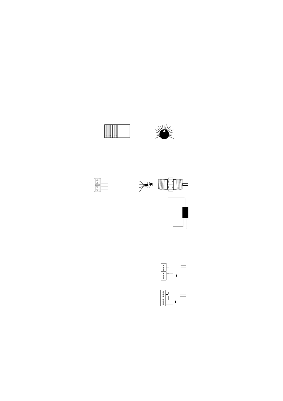
MAIN POWER SUPPLY CONNECTION
•
Before
Before
Before
Before
Before connecting the unit to the mains
connecting the unit to the mains
connecting the unit to the mains
connecting the unit to the mains
connecting the unit to the mains, make sure
that the controller is completely wired
controller is completely wired
controller is completely wired
controller is completely wired
controller is completely wired and that all
connections for pump, alarm, electrode, etc. have been made.
• For 220-240V, short the L1 and N1 termi-
nals. Then wire the external power supply
to the three terminals as shown.
• For 110-115V, short the L and L1 termi-
nals
and the N1 and Neutral. Then wire
the external power supply to the three
terminals as shown.
• Replace the cover with the gasket and screw it tight with the 4
screws provided. Only then
Only then
Only then
Only then
Only then connect the controller to the mains.
1
2
3
Neutral
Line
POWER
SUPPLY
220 VAC
Configuration
L
L1
N1
Neutral
Line
POWER
SUPPLY
L
L1
N1
110 VAC
Configuration
110 VAC
Configuration