1 general data – Glow-worm Ultimate 80FF User Manual
Page 7
7
2000225233B
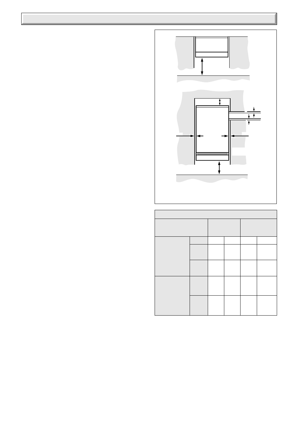
Diagram 1.3
500mm
Additional clearances may be
required for installation
65mm
6mm
6mm
FRONT
VIEW
100mm
0081M
SIDE OR
REAR FLUE
5mm
5mm
1 General Data
1.9 Drain
System
A drain tap must be provided at the lowest points of the system
which will allow the entire system, boiler and hot water cylinder
be drained.
Draining taps should be to the current issue of BS2879.
Boiler
A draining point is fitted at the bottom right hand side of the heat
exchanger.
Cover controls to avoid water damage.
If required remove the combustion chamber front cover to
improve access.
1.10 Safety Valve
A safety valve need not be fitted to an open vented system.
1.11 Location
This boiler is not suitable for outdoor installation.
This boiler is suitable for installation in bathroom zones 2 and 3.
The boiler may be installed in any room, although particular
attention is drawn to the requirements of BS7671 with respect
to the installation of a boiler in a room containing a bath or
shower. Any electrical switch should be so positioned that it
cannot be touched by a person using the bath or shower. The
electrical provisions of the Building Standards (Scotland)
Regulations apply to such installations in Scotland.
In GB this is the current I.E.E. WIRING REGULATIONS and
BUILDING REGULATIONS.
In IE reference should be made to the current edition of I.S.813
"Domestic Gas Installations" and the current ETCI rules.
The boiler must be mounted on a flat wall which is sufficiently
robust to take its total weight.
The boiler may be fitted to a wall made of combustible material.
1.12 Boiler Clearances
Refer to diagram 1.3.
This boiler must be positioned so that at least the minimum
operational and servicing clearances are provided.
Additional clearances may be required for installation.
If fixtures are positioned next to the boiler they should be made
removable for access to pipework.
At least a minimum of 500mm clearance must be left in front of
the boiler for servicing, see diagram 1.3.
1.13 Room Ventilation
The boiler is room sealed and does not require the room or
space containing it to have permanent air vents.
1.14 Boilers in a Compartment
Where the installation of the boiler will be in an unusual position,
special requirements are needed, the current issue of BS6798
gives detailed guidance on these requirements.
A compartment used to enclose the boiler must be designed
and constructed specifically for this purpose. An existing
cupboard or compartment modified for the purpose may be
used. Details of essential requirements for cupboard or
compartment design are given in the current issue of BS6798.
The doorway opening should be of sufficient size to allow for
easy removal of the boiler.
Where the boiler is fitted in a cupboard or compartment,
permanent high and low level ventilation must be provided. The
minimum ventilation areas required are given in Table 2.
1.15 Timber Frame Building
If the boiler is to be installed in a timber frame building it should
be fitted in accordance with the Institute of Gas Engineers
document IGE/UP/7/1998. If in doubt seek advice from the local
gas undertaking or Glow-worm.
1.16 Heating System Controls
The heating system should have installed: a programmer and
room thermostat controlling the boiler.
Thermostatic radiator valves may be installed, however they
must not be fitted in a room where the room thermostat is
located.
NOTE: For further information, see the current issue of the
Building Regulations, approved document L1, and the
references:
1) GIL 59, 2000: Central heating system specification (CheSS)
and
2) GPG 302, 2001: Controls for domestic central heating
system and hot water. BRECSU.
TABLE 2. COMPARTMENT AIR VENTS
VENTILATION
HIGH LEVEL LOW LEVEL
REQUIREMENTS
VENT AREA
VENT AREA
VENTILATION
FROM ROOM
OR SPACE
VENTILATION
FROM
OUTSIDE
MODEL
cm
2
in
2
cm
2
in
2
80FF
264
41
264
41
70FF
231
35
231
35
80FF
264
41
264
41
70FF
231
35
231
35
80FF
132
21
132
21
70FF
116
18
116
18
80FF
132
21
132
21
70FF
116
18
116
18
MINIMUM CLEARANCES FROM WALLS, CEILING,
FLOOR, CUPBOARD, WORKTOPS, AND
INFLAMMABLE MATERIALS