5 boiler installation – Glow-worm Ultimate 80FF User Manual
Page 20
20
2000225233B
Diagram 5.10
4619
3310
5 Boiler Installation
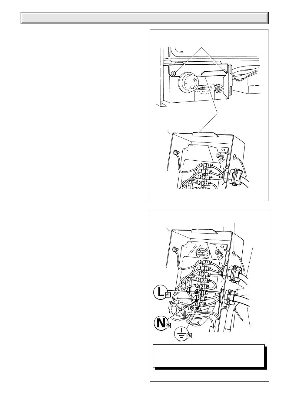
5.7 Electrical Connection
WARNING: This boiler must be earthed.
Take care not to damage any internal wiring and capillaries.
Take plastic cable retaining clip, from the loose items pack, peel
off the backing paper and position it in a suitable place to secure
the incoming cable.
Using heat resistant (to 85
o
C) cable of at least 0.75mm
2
(24/
0.2mm) to the current issue of BS6500 Table 16 and of suitable
length, thread through cable clamps, secure into the plastic
clips and connect to appropriate terminals, see diagram 5.9 and
9.5.
Standard colours are, brown - live (L), blue - neutral (N) and
green and yellow - earth (E).
The mains cable outer insulation must not be cut back external
to the cable clamp.
Make sure the cable is suitably secured.
When making connections, make sure that the earth conductor
is made of a greater length than the current carrying conductors,
so that if the cable is strained the earth conductor would be the
last to become disconnected.
5.8 Pump Connection
The pump must be connected directly to the control box, as
shown in diagram 5.9 threading the cable through the cable
clamp in the side of the control box.
5.9 External Controls
Any external controls must only be wired to interrupt the red link
between terminals SL and 9.
Make sure that the supply cable and all external cables are
secured and away from hot surfaces.
5.10 Testing
Checks to ensure electrical safety must be carried out by a
competent person.
After installation of the system, preliminary electrical system
checks as below should be carried out.
1. Test insulation resistance to earth.
2. Test continuity and short circuit of all cables,
3. Test the polarity of the mains.
The installer is requested to advise and give guidance to the
user on the controls scheme used with the boiler.
Remove red link between 9 & SL when fitting
a time control etc (if no switch is fitted, link will
make the circulation pump run constantly).
FIXING SCREWS
LIP BRACKET
IGNITION
LEAD
PUMP
CABLE
CABLE
CLAMPS
MAINS
CABLE
4620
Diagram 5.8