8 servicing – Glow-worm Ultimate 80FF User Manual
Page 25
25
2000225233B
8 Servicing
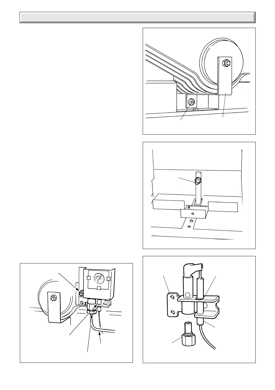
Diagram 8.4
Diagram 8.5
Diagram 8.6
SECURING
SCREW
MAIN
BURNER
INJECTOR
PILOT
BURNER
SPRING
CLIP
ELECTRODE
PILOT
INJECTOR
4112
4111
4143
Remove the main burner from the main injector at the rear.
Raise the burner up and forwards, easing the pilot pipe down,
to clear, take care not to damage the combustion chamber
insulation or the pilot p[pipe.
Use a vacuum cleaner or suitable stiff brush to clean the burner
thoroughly, making sure that all the burner ports are clear and
unobstructed.
Continue cleaning heat exchanger as Section 8.2.
NOTE: On refitting and after cleaning the heat exchanger make
sure the burner is fitted correctly, that is, located on the main
injector and horizontal.
8.4 Main Injector
With the main burner removed the main injector can be inspected
and cleaned as necessary, see diagram 8.5.
If removing for cleaning do not use a wire or sharp instrument
on the hole.
Use a little suitable sealant on the external thread when refitting
making sure a gas tight seal is made.
8.5 Pilot Burner/Electrode and Pilot Injector
Clean the pilot burner and electrode.
To remove the electrode release the spring clip, see diagram
8.6.
When removing and replacing the pilot injector from the pilot
burner take care not to damage the electrode, see diagram 8.6,
clean the injector by blowing through it.
Check that the spark gap is as shown in diagram 6.4.
8.6 Operational Checks
After completing a service and before fitting the case, check
condition of the case seal and renew if necessary.
Examine flue hood and terminal to make sure they are clean and
clear of obstructions.
Light the boiler and carryout the functional checks as described
in Section 6.
Testing Flue Gases: If any doubt exists that the flue products
are not exhausting correctly, investigate by use of a gas
analyser (FGA).
Diagram 8.3
BURNER SUPPORT
SCREW
SECURING NUT AND
SHAKEPROOF
WASHER
PILOT PIPE
ELECTRODE AND
LEAD ASSEMBLY
UNION
CONNECTOR
4109