4 flue and appliance preparation – Glow-worm Ultimate 80FF User Manual
Page 14
14
2000225233B
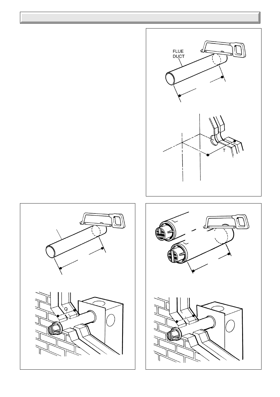
Diagram 4.6
Diagram 4.7
Diagram 4.8
FLUE
DUCT
LONG FLUE
TERMINAL
STANDARD FLUE
TERMINAL
Q PLUS 5mm
Q
BOILER
CENTRE
LINE
T MINUS 188mm
6833
6831
6829
4 Flue and Appliance Preparation
Drill holes and plug, to suit No.12x2in woodscrews, fit the
screws allowing sufficient clearance, about 5mm, to accept the
swing brackets, see diagram 4.5.
Secure the mounting bracket to the wall with No.12x2in
woodscrews and plugs, see diagram 4.5.
4.7 Flue Duct
Mark the duct to the length required, this length allows for
expansion, see diagram 4.6 for rear flue and diagram 4.7 for
side flue, then cut square and remove any burrs.
4.8 Air Duct/Terminal
Mark the duct length, see diagram 4.8 for rear flue and diagram
4.9 for side flue, then cut square and remove any burrs.
4.9 Air Duct/Terminal and Flue Duct Assembly
Locate the flue duct into the air duct/terminal, see diagram 4.10.
Take the flue manifold from the loose items pack together with
the sealant. Place the sealant onto the flue manifold.
Fully locate the flue manifold in to the air duct/terminal and flue
duct assembly as shown in diagram 4.10, make sure the correct
alignment of the “Top”s.
Drill two 3mm diameter holes through the air duct/terminal to the
flue manifold secure with the two self tapping screws supplied
in the loose items pack.
It should now not be possible to remove the manifold.
Q