10 replacement of parts – Glow-worm Ultimate 80FF User Manual
Page 32
32
2000225233B
10 Replacement of Parts
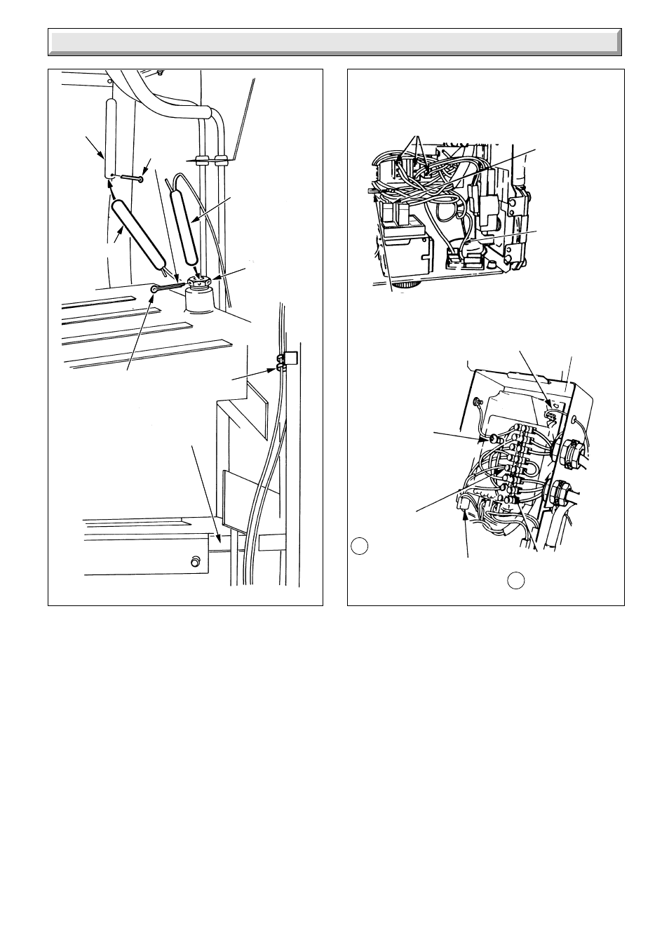
10.4 Control Board (PCB) - diagram 102A
Release the control box, refer to Section 5.6.
Disconnect the three electrical plugs and ignition lead.
Release the cables from the plastic retaining clip, then disconnect
the cables from the PCB to the main terminal strip, control
thermostat and earth connection.
Release the main terminal strip and plastic label.
Carefully pull the board away from its supports.
When refitting refer to wiring diagram 9.5.
10.5 Pilot Burner and Pilot Injector
Proceed as Section 8.3 and 8.5.
10.6 Electrode
Proceed as Section 8.3 and 8.5.
Gain access as Section 5.6 to remove lead from control box.
Diagram 10.2
Diagram 10.2A
PHIAL
POCKET
THERMOSTAT
PUMP
OVERRUN
PHIAL
ELECTRICAL PLUGS
CHASSIS
EARTH
CONNECTION
MAIN
TERMINAL
STRIP
SECURING
SCREW (2)
ELECTRICAL
CONNECTION
SL BROWN CABLE
PLASTIC
RETAINING
CLIP
ELECTRICAL
CONNECTION
N BLUE CABLE
SPLIT
PIN
GLAND SEAL
(Right hand illustrated)
SUPPORT
POST (4)
IGNITION
LEAD
SPLIT
PIN
PHIAL
POCKET
RETAINING
CLIP
4110
BOILER
THERMOSTAT
ELECTRICAL
CONNECTION
NO.3"YELLOW"
CABLE
OVERHEAT
CUTOFF
DEVICE
PHIAL
NOTE: All capillaries and
cables should be
situated within the
"Gland Seal".
3328
5756
OVERHEAT
CUTOFF
ELECTRICAL
CONNECTION
"WHITE"
CABLE