5 boiler installation – Glow-worm Ultimate 80FF User Manual
Page 18
18
2000225233B
5 Boiler Installation
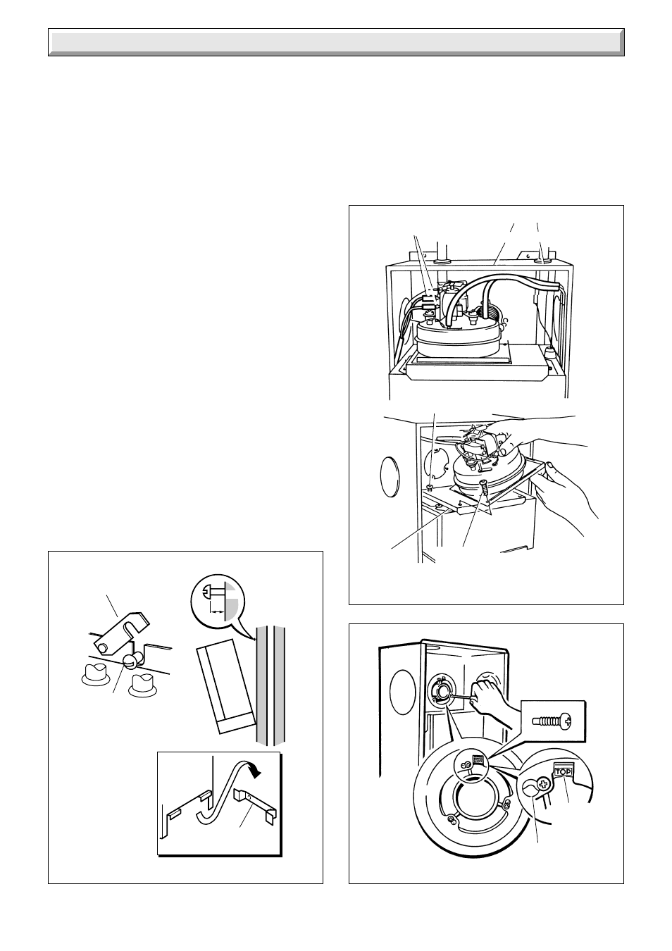
Diagram 5.4
ELECTRICAL
CONNECTIONS
REAR SECURING SCREW (2)
(SLACKEN but do not remove)
GASKET
4086
AIR PRESSURE TUBES
CLEAR RED
SECURING
SCREW (2)
0167(a)M
Diagram 5.3
5mm
MOUNTING
BRACKET
SWING
BRACKET
SECURING
SCREWS (2)
NOTE:
PIPES REMOVED
FOR CLARITY
5.3 Water Circulation System
Complete the water connections to the boiler.
Fill, vent and flush the system.
Check for any water leaks and put right.
5.4 Safety Valve Discharge
Fit a suitable discharge pipe to the safety valve and route it to
outside the building so that any discharge can be seen but will
not cause injury to persons, damage to property or any electrical
installation.
5.5 Gas Connection
Make the gas connection to the Rc
1
/
2
in gas service cock, see
diagram 6.1.
Check for leaks using a suitable leak detection fluid.
The whole of the gas installation, including the meter, should be
inspected, tested for soundness and purged in accordance with
the current issue of BS6891 and in IE the current edition of I.S.
813 "Domestic Gas Installations".
5.6 Control Box Removal
Remove the electrical control box securing screws, see diagram
5.8. Slide the box forwards and release, hook it onto the lip
bracket at the front, see diagram 5.8.
Diagram 5.5
KEYHOLE
LOCATION
LUG
4134