3 water systems, 13 domestic hot water cylinder, 14 domestic hot water system - unvented – Glow-worm Ultimate 80FF User Manual
Page 11: 15 filling a sealed water system, 16 water makeup
11
2000225233B
METHOD 1
METHOD 2
METHOD 3
SUPPLY STOP
VALVE
SUPPLY
PIPE
HOSE
UNIONS
SERVICING
VALVE
TEMPORARY
HOSE
HEATING
SYSTEM
HEATING
SYSTEM
TEMPORARY
HOSE
HOSE
UNIONS
SERVICING
VALVE
SUPPLY
PIPE
SUPPLY STOP
VALVE
DOUBLE CHECK
VALVE ASSEMBLY
HEATING
SYSTEM
SERVICING
VALVE
SUPPLY
STOP VALVE
SUPPLY
PIPE
HOSE
UNIONS
DOUBLE CHECK
VALVE ASSEMBLY
OVERFLOW
CISTERN
COMBINED
CHECK VALVE
AND VACUUM
BREAKER
PRESSURE
REDUCING
VALVE
0051M
Diagram 3.4
3 LITRES (0.66 gals)
MAKE-UP BOTTLE
(if required)
NON-RETURN
VALVE
AUTO
AIR
VENT
FLOW
DRAIN
COCK
BOILER
SAFETY
VALVE
(Make-up
alternatives)
EXPANSION
VESSEL
PRESSURE
GAUGE
CIRCULATING
PUMP
FILLING POINT
AIR
RELEASE
POINT
HEATING
CIRCUIT
IF REQUIRED
22mm (min)
BY-PASS WITH
LOCKSHIELD
VALVE
RETURN
6465
3 Water Systems
Diagram 3.5
3.13 Domestic Hot Water Cylinder
SINGLE FEED INDIRECT CYLINDERS ARE NOT SUITABLE.
The domestic hot water cylinder must be of the indirect coil type.
It must be suitable for working at a gauge pressure of 0.35bar
above the safety valve setting.
3.14 Domestic Hot Water System - Unvented
Where a storage system will not have a vent to atmosphere the
installation must comply with Building Regulations and local
Water Company Bye-laws, see also the current issue of BS6700.
If fitting into an existing system the local authority must also be
advised.
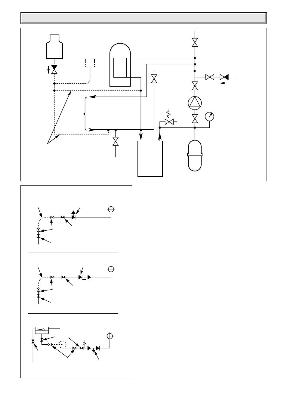
3.15 Filling a Sealed Water System
Provision for filling the system at low level must be made. Three
methods are shown in diagram 3.5. There must be no permanent
connection to the mains water supply, even through a non-
return valve.
3.16 Water Makeup
Provision must be made for replacing water lost from the
system. A make up vessel mounted above the highest point of
the system and connected through a non-return valve to the
system on the return side of either the hot water cylinder or
heating system, see diagram 3.4.
Alternatively provision for make up can be made by a filling loop.