8 two collector flashing kit - 15 – Glow-worm Clearly Solar Vertical In-Roof Collector User Manual
Page 32
32
14975
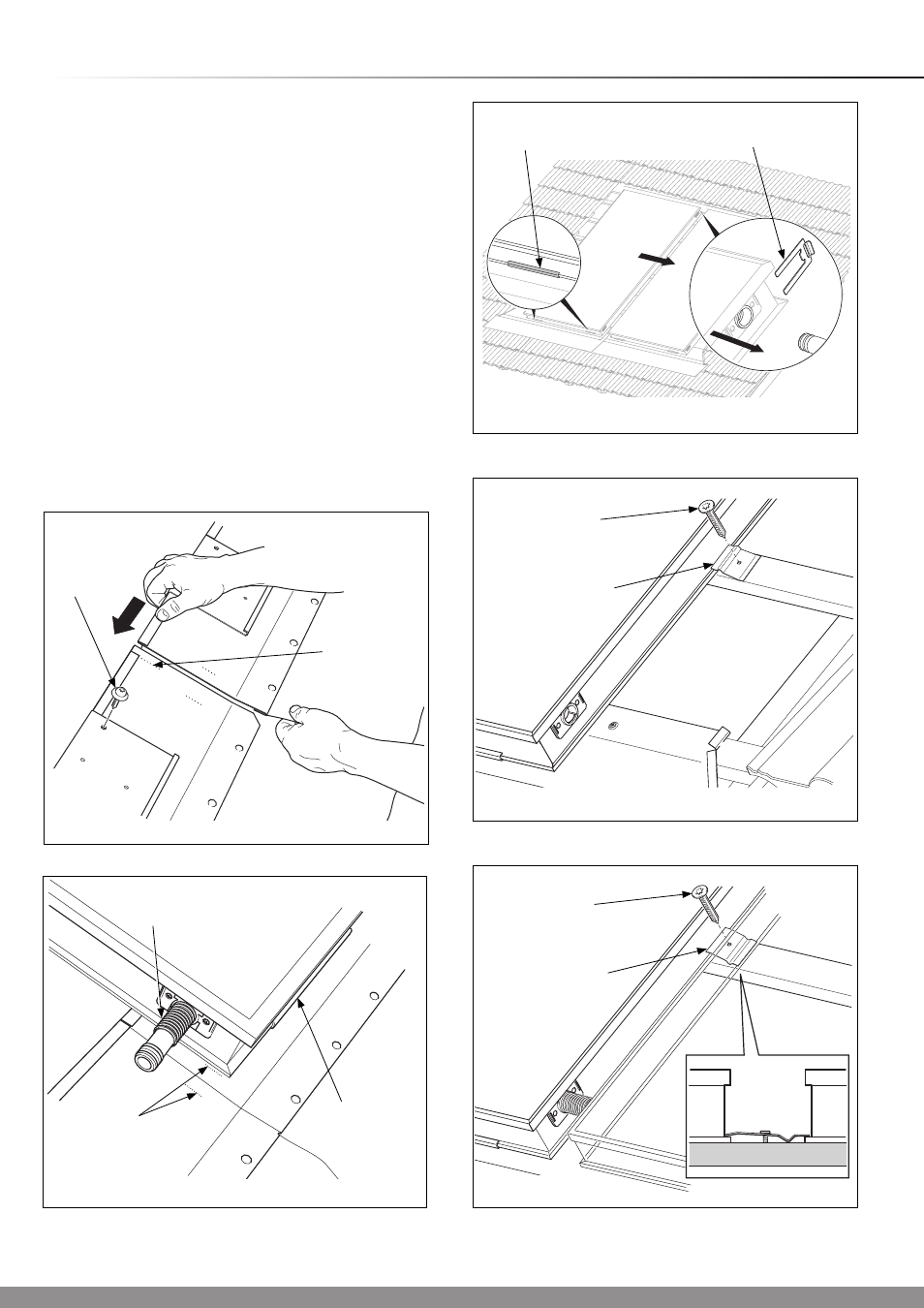
Diagram 8.4
SCREW
(No.1)
ALIGNMENT
MARK
14969
LOCATION
CHANNEL
ALIGNMENT
MARKS
PIPE
COUPLING
Diagram 8.5
Slide the right front section up to the mark on the left front
section, see diagram 8.4. With six securing screws (no.1),
screw the right front section to the roof batten using the
supplied Torx bit.
Position the collector panel protective side uppermost into the
location channel as shown in diagram 8.5.
NOTE: The design is symmetrical and does not have a top or
bottom.
Insert the pipe couplings into the hydraulic socket connection.
The pipe coupling should be inserted up to the stop.
Place the next collector into its position as previously
described, then push the collector, ensuring engagement of
the pipe coupling, see diagram 8.6, and align with the marks
on the flashing.
With the screws (No.3) and clamps and Torx bit supplied,
secure to the roof battens, see diagram 8.7.
For securing between collectors the inner clamp should be
secured as shown and grip both collector edges, see diagram
8.8
Diagram 8.6
14951
RETAINING
CLIP
Diagram 8.7
14974
INNER CLAMP
SCREW
(No.3)
8 Two Collector Flashing Kit - 15
0
- 22
0
LOCATION
CHANNEL
Diagram 8.8
15195
INNER CLAMP
SCREW
(No.3)