7 one collector extension kit - 22 – Glow-worm Clearly Solar Vertical In-Roof Collector User Manual
Page 26
26
With regards to the hydraulic system you have chosen, insert
and secure the hydraulic connections, see diagram 7.9.
Insert the collector sensor into the appropriate elbow (flow,
top), see diagram 7.9. The collector sensor is packed with the
Fluropro controller, part no. 0020054960.
Mount the plug with the bleed valve in the opposite top
position.
Connect the collector to the system circuit.
Ensure that all of the following steps have been performed:-
- All the connections have been fixed with securing clips.
- All hydraulic connections laid properly.
- The collector sensor has been connected.
- The collectors are connected to a lightning protection
device.
- A pressure test.
- All insulation is intact.
NOTE: After initial commissioning and according to the
season, high outside temperature oscillations can cause
condensation in the collector, this is normal.
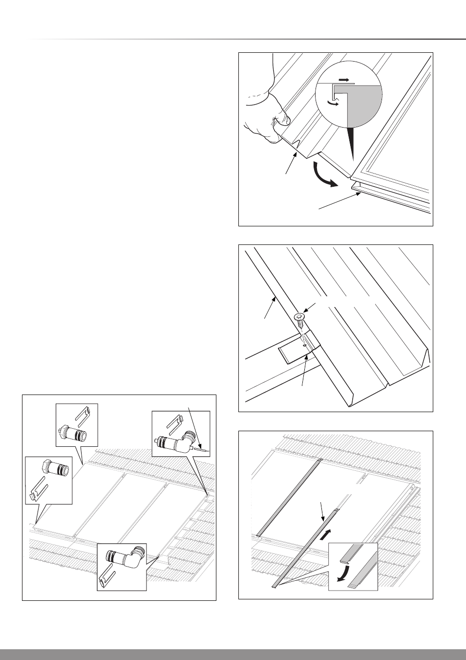
Fit the side sections to the collector frame, ensure that they
are pushed into place on the upper collector edge, see
diagram 7.10.
Secure the side sections to the roof battens with the supplied
clamps and screws (No. 2) using the supplied Torx bit, see
diagram 7.11.
Slide the intermediate plate from below and between the
collectors, until it is flush with the lower collector edge, see
diagram 7.12.
NOTE: If it’s not possible to mount the intermediate plate
from below (because of dormers, etc.), carefully bend up the
intermediate plate (see inset diagram 7.12), slide the plate
from the top between the collectors and bend it down again.
Diagram 7.9
15033
Diagram 7.10
14979
SIDE
SECTION
COLLECTOR
Diagram 7.11
14978
EXTERNAL
CLAMP
SIDE
SECTION
SCREW (No.2)
Diagram 7.12
15034
7 One Collector Extension Kit - 22
0
- 75
0
INTERMEDIATE
PLATE
COLLECTOR SENSOR