6 two collector flashing kit - 22, 2 support plates/board – Glow-worm Clearly Solar Vertical In-Roof Collector User Manual
Page 20
20
max 150
No.3
No.2
14959
Diagram 6.14
14960
Diagram 6.15
14961
RIDGE
PLATE
Diagram 6.16
14962
No.5
No.1
RIDGE PLATE
COUPLING
COLLECTOR FRAME
SLOT
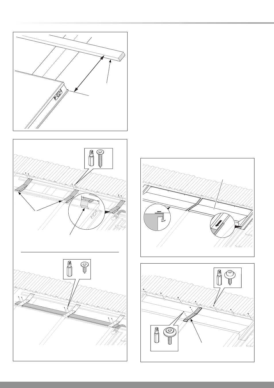
6.2 Support plates/board
Fix the top batten into position as shown in diagram 6.13.
Mount the support plates above the collector:
- one on the external edge (max. 150 mm from the edge)
- one per collector joint (central).
Make sure that the support plates are on the collector frame
slot, see diagram 6.13.
Fix the support plates to the top roof batten with two screws
(No.3) using the supplied Torx bit.
Slide the board through the support plates.
Fix the board to the support plates with two screws (No. 2)
using the supplied Torx bit, see diagram 6.14.
Slide the ridge plates on the support plates, see diagram 6.15.
Make sure that the ridge plates are above the side sections
and engaged in the corresponding rail (
A).
Fix the ridge plates to the roof battens with the screws (No. 1)
using the supplied Torx bit.
Fix the ridge plate coupling to the ridge plate joint with three
screws (No. 5) using the supplied Torx bit, see diagram 6.16.
6 Two Collector Flashing Kit - 22
0
- 75
0
SUPPORT
PLATES
Diagram 6.13
15308
350mm
TOP
BATTEN
A