5 single collector flashing kit - 22 – Glow-worm Clearly Solar Vertical In-Roof Collector User Manual
Page 12
12
5 Single Collector Flashing Kit - 22
0
- 75
0
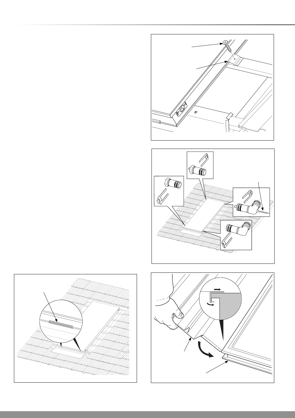
Position the collector, protective side uppermost into the
location channel as shown in diagram 5.4.
NOTE: The design is symmetrical and does not have a top or
bottom.
Secure the collector with the clamps and screws provided, see
diagram 5.5.
With regards to the hydraulic system you have chosen, insert
and secure the hydraulic connections, see diagram 5.6.
Insert the collector sensor into the appropriate elbow (flow,
top), see diagram 5.6. The collector sensor is packed with the
Fluropro controller, part no. 0020054960.
Mount the plug with the bleed valve in the opposite top
position.
Connect the collector to the system circuit.
Ensure that all of the following steps have been performed:-
- All the connections have been fixed with securing clips.
- All hydraulic connections laid properly.
- The collector sensor has been connected.
- The collector is connected to a lightning protection device.
- A pressure test.
- All insulation is intact.
NOTE: After initial commissioning and according to the season,
high outside temperature oscillations can cause condensation
in the collector, this is normal.
Fit the side sections to the collector frame, ensure that it is
pushed into place on the collector edge, see diagram 5.7.
Diagram 5.6
15023
Diagram 5.7
14979
SIDE
SECTION
COLLECTOR
Diagram 5.5
14974
CLAMP
SCREW
(No.3)
Diagram 5.4
15026
COLLECTOR
SENSOR
LOCATION
CHANNEL