Introduction – Glow-worm Clearly Hybrid - Universal Module System User Manual
Page 9
0020096317_01 - 02/11 - Glow-worm
- 7 -
Key
1 Overheating safety (UFH shown, but can be underfl oor or radiators)
2 Hydraulic
module
3 Heating
circuit
4 Climapro2 RF programmable wireless room thermostat
5 Systempro control unit
6 Wireless outside sensor with solar panel
7 CAll brands of boiler controlled by 24V ON/OFF contact
8 Heat pump electrical supply + protection (This must have it's own
single isolation)
9 Non-return valve (recommended to prevent burner ignition triggered
by thermo-siphoning)
10 EBus heat pump
11 Heat pump circuit fi lter (not supplied)
12 Glycol PRV discharge
A Heating circuit return
B Heating
circuit
fl ow
C Boiler circuit return
D Boiler
circuit
fl ow
E
Heat pump circuit fl ow
F
Heat pump circuit return
G Heat pump circuit safety valve discharge
Application conditions
- The Systempro control unit manages the operation of the
boiler, the heat pump and the module.
- The Systempro control unit manages up to 3 heating zones.
- Each wireless room thermostat can control a heating zone.
- Boiler must have a 24V thermostat input.
- The installation can be performed with a low-temperature
underfl oor heating (heating outlet temperature < 50°C) or low
temperature radiators (heating outlet temperature < 70°C).
e
Use 0.75 mm² section cables for the electrical
connections to the control unit.
Control unit settings
Description of main settings
Setting
Diagram no.
3
Did you install a multizone kit ?
No
Heating curves
0.1 - 1.5
Max. heating fl ow temperature
30°C < T < 70°C
Energy effi ciency ratio
To be defi ned
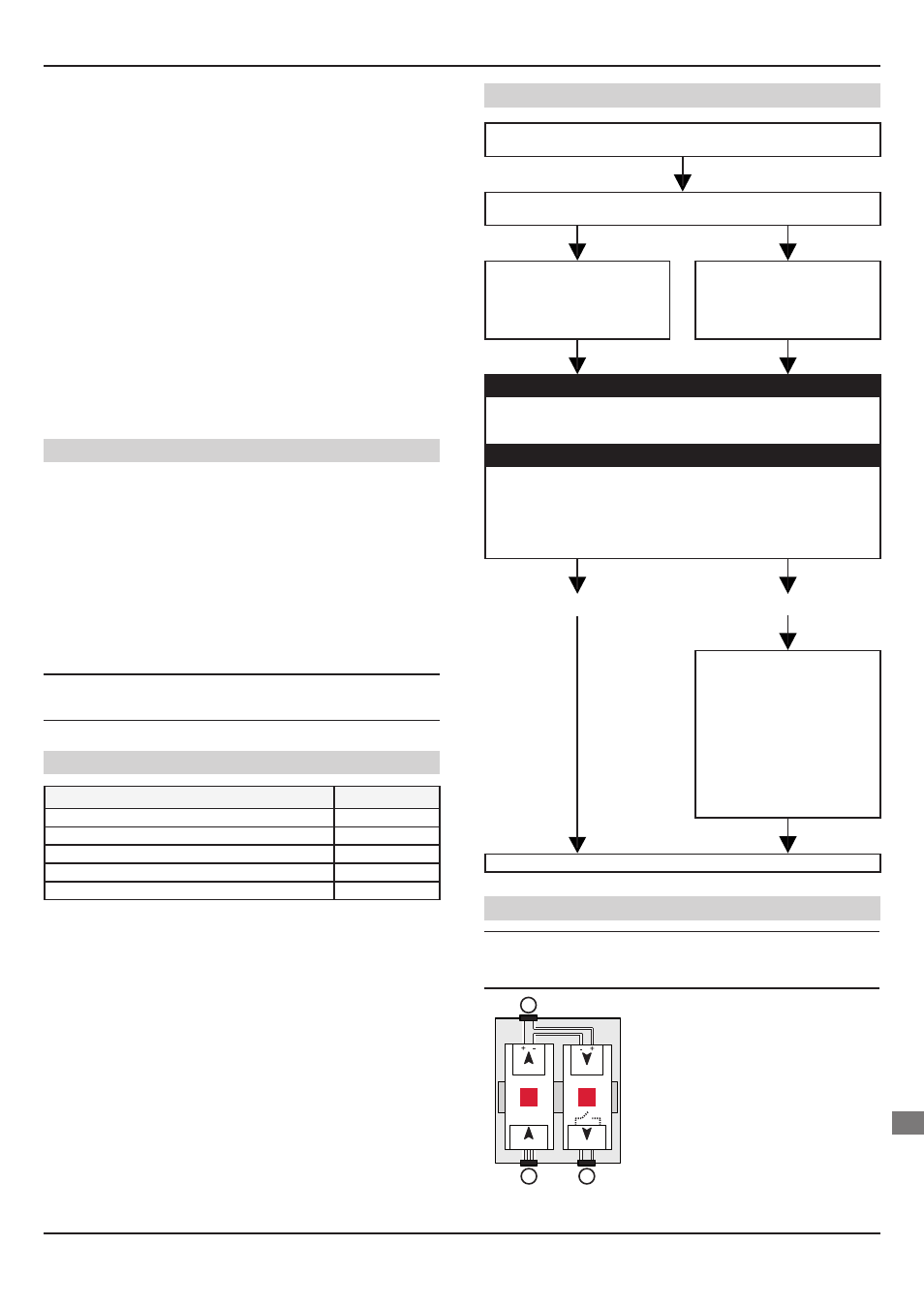
Connecting the boiler
If a room thermostat is already connected to an existing boiler, remove
it.
Check whether the room thermostat is connected to a boiler 24V or
230V input.
24V = Connect the boiler 24V
thermostat input to the "OUT1"
connector of the control unit.
230V = Refer to the “Diagram
13" section
or install a
24V/230V converter
(see below).
In the case of an existing boiler without external sensor:
Increase the boiler heating outlet temperature by 5°C.
Ensure that the heating outlet temperature does not exceed 70°C (50°C
in the case of a underfl oor heating).
In the case of an existing boiler with external sensor:
Keep the existing boiler heating curve if the comfort of the existing
installation is satisfactory.
Ensure that the heating outlet temperature does not exceed 70°C (50°C
in the case of a underfl oor heating).
Important: the setting of the control unit heating curve must be identical
to that of the boiler.
OK
NOK
Ensure that the heating outlet
temperature does not exceed
70°C (50°C in the case of a
underfl oor heating).
> If the adjustment is not
available on the boiler, perform
it on the thermostatic valve.
> If there isn’t a thermostatic
valve, install a temperature
control device to make this
adjustment.
Put the installation into service.
Connection of a 24V/230V converter (not supplied)
e
Attention: risk of signifi cant current draw. Check
the power consumption of the component (pump,
burner...) check the 230V boiler thermostat input.
230VAC
24VDC
24VDC
230VAC
A
B
C
1
2
Legend
1 230VAC / 24VDC transformer
2 24VDC / 230VAC relay
A Connection to 230VAC power
B Connection to control unit OUT1
connector
C Connection to the 230V thermostat
connection of a boiler controlled by
contact
INTRODUCTION
EN