Maintenance – Glow-worm Clearly Heat Pumps 5kW User Manual
Page 24
0020096879_01 - 06/10 - Glow-worm
- 22 -
MAINTENANCE
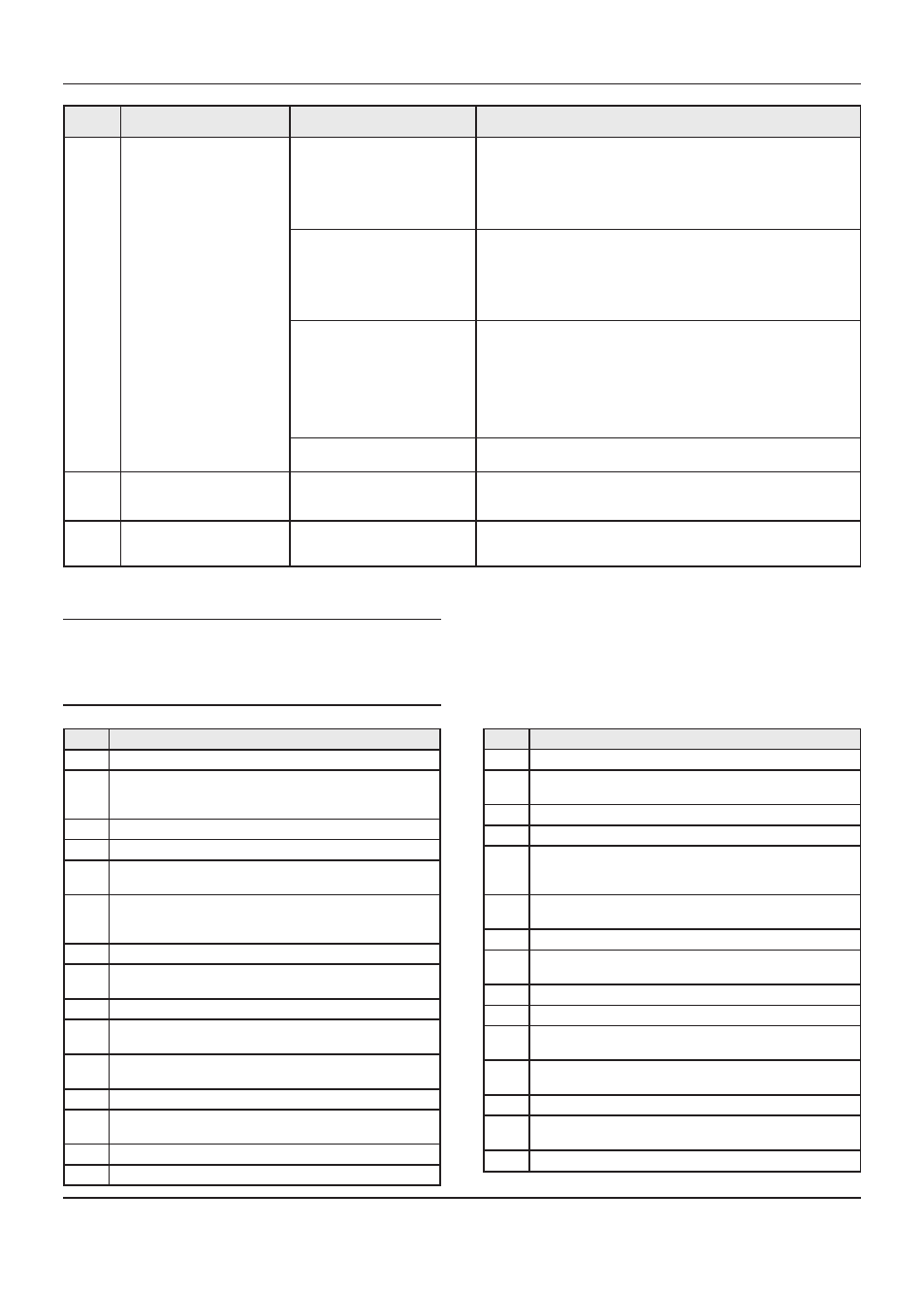
fault
codes Description
Cause
Solution
584
The compressor discharge
temperature does not rise
(<5k in 2 minutes).
Blocking fault if it occurs 3
times in 10 compressor starts.
Failure in compressor power
supply.
Check the compressor’s connections.
Check the condition of the compressor’s cables.
Check the compressor’s 230 V power supply at the main PCB.
Check that the compressor’s electrical resistance is working properly.
Replace the compressor, make sure there are no leaks.
Add oil to the compressor if necessary.
The compressor’s bimetallic strip
is open.
Check that the 4-way valve is not blocked (switch the heat pump ON /
OFF).
Check that the electronic expansion valve is working properly. If it not
working correctly, check the winding resistance.
Replace the motor.Clip the electronic expansion valve back on.
Replace the electronic expansion valve, check that there are no leaks.
Lack of refrigerant.
Measure the air and water’s ΔT. If it is very low (<2K), lack of fluid
may be the cause (loss of heat output). Measure the real overheating
(must be <7K in heating mode). Measure the electrical current with an
ammeter. If the current is below 4.5 amps, the cause may be a lack of
fluid.
Check the pressure with a monometer.
Check that there are no leaks, repair them if necessary.
Adjust the amount of refrigerant.
Failure of the compressor
discharge temperature sensor.
Check the position of the compressor discharge temperature sensor.
Add thermal grease.
585
Failure of the air exchanger air
intake temperature sensor.
The sensor is defective or is not
correctly plugged in to the main
PCB.
Check the sensor’s connections. Check that the position and the
operation of the sensor are correct.
Check the sensor’s resistance.
774
Air intake temperature sensor
fault.
The sensor is defective or not
correctly connected to the main
circuit board.
Check the sensor connections. Check that the sensor position and
operation are correct.
Check the sensor resistance.
15.2.1
Status of the heat pump
b
All blocking statuses relative to the heat pump
must be resolved. Once resolved, switch the
heat pump On / Off to reset and make sure that
the status is no longer displayed on the control
unit screen.
Status Description
0
Waiting status: no requests, no defects.
1
Waiting status pending a request (pending a correct brine
circuit return temperature, waiting time of 5min OFF,
compressor cycle waiting time).
3
Pre-fan scan (between 10s and 2min).
4
Pre-brine circuit pump scan (30s).
6
In heating mode, start-up of the compressor and regulator
control in accordance with the air temperature (1 min.).
7
Expansion valve check depending on evaporation
temperature. In heating mode, compressor operational
(overheating control, pending end of request).
8
Post-scan following heating (30s).
9
Failure of compressor output temperature, too high (blocking
failure after 3 attempts).
10
Pump cleansing (every 24 hours during 20s).
12
Failure in heating output temperature, too high (temporary
blockage of 10min).
13
Pressure failure in heating mode, low pressure too low
(blocking failure after 4 attempts).
14
Pressure failure (temporary blockage of 10min).
15
High pressure failure (high pressure sensor open 42bar,
blocking failure).
16
40s pre-scan of the hydraulic pump before defrosting.
17
Defrosting in operation (duration 1 to 10min).
Status Description
18
40s post-scan of the hydraulic pump after defrosting.
19
Failure of outgoing and return temperature difference > 15°C
(temporary blockage 10min).
20
Water flow failure, too low (temporary blockage 10min).
21
Fan failure: speed too low (temporary blockage 15min).
23
Failure of compressor output temperature: does not surpass
2K in less than 2 minutes upon start-up of compressor
(blockage 10min).
24
Bad flow rate in the heat pump circuit (refer to the following
table for details of this status).
25
Temperature sensor failure.
26
Heat pump circuit return temperature too high (refer to the
following table for details of this status).
27
Heat pump circuit pump pre-sweep in cooling mode.
28
Fan pre-flush in cooling mode (between 10s and 2 min).
29
Compressor start in cooling mode (1 minute wait for
temperature stabilisation).
30
Compressor operating in cooling mode (overheat control,
waiting for end of request or setting reached).
31
Post-sweep of the pump after cooling.
32
Air temperature not suitable for heat pump start (refer to the
following table for details of this status).
33
Degassing of pump (30s ON).