Installation – Glow-worm Clearly Heat Pumps 5kW User Manual
Page 17
0020096879_01 - 06/10 - Glow-worm
- 15 -
INSTALLATION
The manufacturer declines any responsibility for damages to
persons or others caused by the incorrect installation of the
appliance earthing. This includes failure to comply with current
standards.
Electrical components have been tested to meet the equivalent
requirements of BSEN 7671 and the BEAB regulations.
The cables connecting the switchboard and the heat pump must
be:
- Suitable for a fixed installation.
- weather resistant.
- equipped with wires adapted to appliance’s power rating.
• Connect the heat pump to an electrical panel via an
independent protection system (20A differential breaker with
at least 3 mm between each contact).
Additional protection may be required during installation to
ensure surge category II.
11.1 Main board
20 mm max.
1
2
Key
1 Electrical wires
2 Insulation
When you connect the electrical wires to a connector on the
electronic board:
• Keep a distance of a maximum of 20 mm between connector
and the start of the insulation (2).
11.2 Access to main board
B
A
2
1
Key
1 Handle
2 box
• Remove the box (2) by pulling it toward you using the handle
(1).
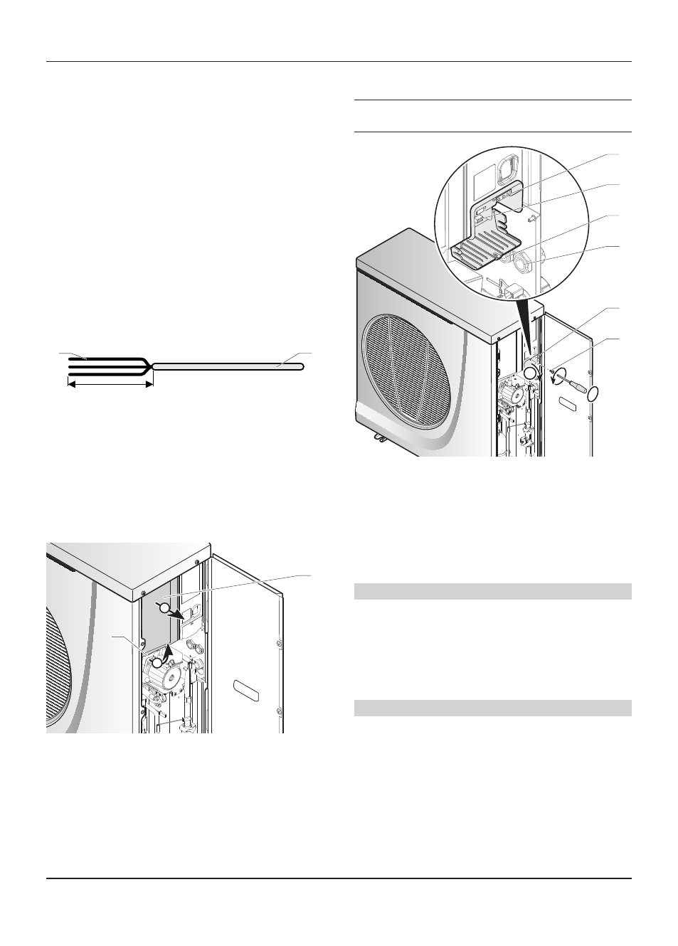
11.3 Electrical wiring
e
Insert the Ebus 24V cable and 230V power cable
in different casings.
B
A
5
4
3
2
1
6
Key
1 230 V supply connection terminal block
2 bUS connection terminal
3 Gland for Ebus cable
4 Gland for 230 V power cable
5 Access hatch to electrical connections
6 Access hatch screw
• Remove the screw (6) from the access hatch (5).
• Open the access hatch (5).
Ebus Connection
• Connect a 2 x 0.75 mm ² cable to the appliance’s BUS
terminal (2).
• Pass the cable through the gland (3).
• Connect the Ebus cable to the system control unit.
• Tighten the gland.
230V Connection
• Connect a 3 x 2.5 mm ² cable to the appliance’s power
terminal 230 (1).
• Pass the cable through the gland (4).
• Connect the appliance’s power cable to the installation’s
electrical panel: single-phase network 230V + neutral +
earth.
• Close the access hatch with the screw (6).
• Tighten the gland.