Maintenance, 15 trouble-shooting – Glow-worm Clearly Heat Pumps 5kW User Manual
Page 20
0020096879_01 - 06/10 - Glow-worm
- 18 -
MAINTENANCE
MAINTENANCE
i
Any work carried out on the refrigerant circuit must
be conducted by qualified engineers.
The faults described in this chapter require the services
of a qualified professional and, if necessary, a Glow-worm
Groupservice engineer.
15 Trouble-shooting
15.1 fault diagnosis
The following checks should be performed before proceeding
onto specific diagnostics:
- Make sure that the electricity supply has not been interrupted
and that the appliance is connected correctly.
- Ensure that the isolating valves are open.
- Check that all external controls are connected correctly.
15.2 fault codes
i
The faults described in this chapter should be
carried out by a qualified engineer or a Glow-worm
Groupservice engineer.
In this section, you will find the fault codes that may appear and
the corrective actions you can take to return the appliance to
service.
In the case of a fault, the fault code number is displayed on the
control unit.
• Carry out any necessary repairs.
• Restart the heat pump using the ON / OFF button.
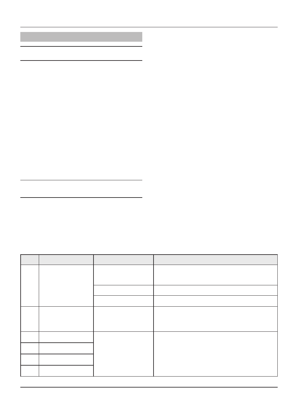
fault
codes Description
Cause
Solution
23
The temperature difference
between the output and the
return of the brine circuit is too
high (> 15K).
Non-blocking failure
Misreading of the circuit
temperature.
Check the plate to plate exchanger return and outgoing temperature
sensor connections. Check that the position and the operation of the
sensor are correct.
Add thermal grease.Check the sensor’s resistance.
The electronic circuit board is not
operating.
Replace the circuit board.
Faulty indication of water flow.
Check that there is no water flow by closing a valve in the brine circuit.
Force the pump and check the flow.
37
The fan speed is too low.
(<300 rpm)
Blocking failure if produced
more than 3 times in the last
10 starts.
The fan speed is too low.
Check the fan connections.
Check the fuses in the main PCB.
Change the electrical panel.
Check the space in front of the fan grill.
Replace the fan motor.
514
Compressor suction
temperature sensor failure.
The sensor is defective or is not
correctly connected to the main
PCB.
Check the sensor’s connections.
Check that the position and the operation of the sensor are correct.
Check the sensor’s resistance.
517
Compressor discharge
temperature sensor failure.
519
Brine circuit return temperature
sensor failure.
520
Brine circuit output
temperature sensor failure.