20 replacement of parts – Glow-worm 30ci Plus User Manual
Page 54
54
4000123944-2
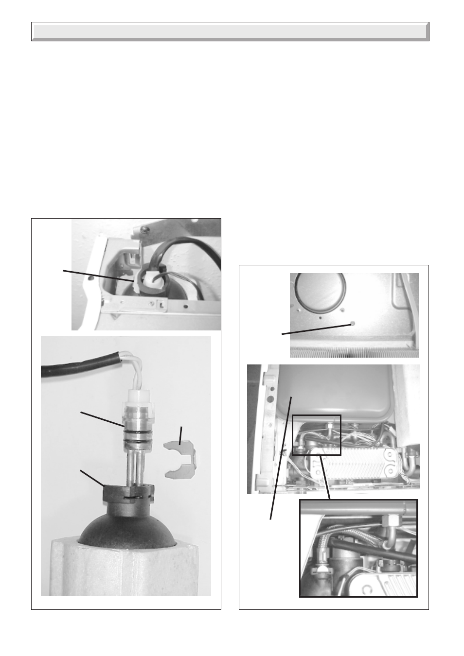
Diagram 20.28
11567
EXPANSION
VESSEL
11568
20 Replacement of Parts
11582
EXPANSION
VESSEL
SECURING
SCREW
vessel of the same specification may be connected as close as
possible to the boiler, leaving the original in position, refer to the
installation instructions.
Replacing the expansion vessel
Before starting refer to the front of Section 20 Important
information.
• For this operation the boiler must be removed from the wall.
• IMPORTANT: With regards to the manual handling operations,
1992 regulations, the following operation exceeds the
recommended weight for one man lift.
• Remove the front panel, refer to Section 17.3.
• Lower the control panel, refer to Section 17.4.
• Drain down the boiler only ,refer to relevant parts of
diagram 20.1.
• Disconnect the flue system.
11577
Diagram 20.27
• Disconnect the boiler pipes at the fixing jig.
• Disconnect the pressure relief valve discharge pipe.
• Disconnect the mains cable and any external controls cables.
• Lift up to remove the boiler from the wall.
• Remove sealed chamber cover, refer to Section 17.4.
• Remove the combustion chamber cover, refer to Section
17.5.
• Remove the fan, refer to Section 17.10.
• Remove air pressure switch sensing tube from the side of the
flue hood, see diagram 17.9.
• Release both side panels, refer to Section 17.6.
• Remove the flue hood, lift up and off to release from rear
location tabs.
• Remove the expansion vessel retaining screw.
• From the rear of the boiler.
• Undo pipe coupling on expansion vessel.
• Lift to remove expansion vessel.
Note: Check that expansion vessel pressure is correct, see
‘Section 1 Technical Data’.
SLOTTED
METAL
CLIP
MICRO
ACCUMULATOR
VESSEL
MICRO
ACCUMULATOR
VESSEL HEATING
ELEMENT
SLOTTED
METAL
CLIP
11565
➜
➜