2 electrical connection of the mx42a control, Figure 3: connection of power terminal – ENMET MX-42A User Manual
Page 8
ENMET Corporation
MX42A C
ONTROL
4
3.2 Electrical Connection of the MX42A Control
Power supply
: connect the power supply wires to the terminal blocks of the Control. Located on the PC Board at the
bottom of the enclosure.
N
OTE
:
Before installation, turn off the
MX 42A C
ONTROL
using the toggle switch,
S2
, located inside the unit in the
bottom left corner.
W
ARNING
:
Continuous gas detection and alarm systems (110
V
AC
/220
V
AC
/ 24
V
DC
/
12
V
DC
powered) become
inoperative upon loss of primary power. Contact factory for specifications and pricing of backup
battery systems.
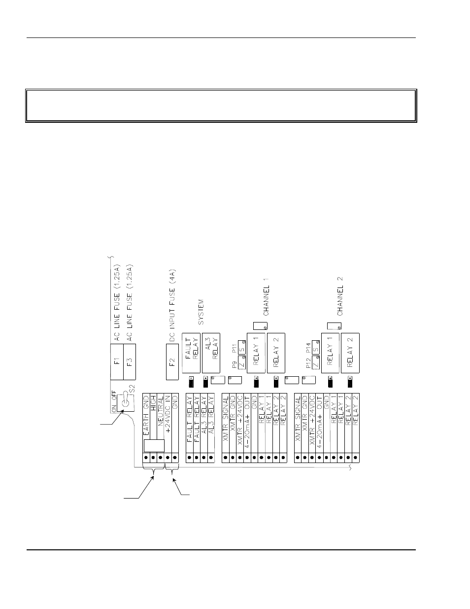
See Figure 3 for the connection of the power terminals.
•
AC, Ground labeled
TERRE
on the board
AC, High labeled
PHASE
on the board
AC, Neutral labeled
NEUTRE
on the board
terminals, 115
V
AC
(103 V to 122 V), 50/60 Hz, are protected by
F1
and
F3
with 1.25A time-delay fuses.
•
+ DC labeled +
CONTINU
on the board
– DC labeled –
CONTINU
on the board
terminals, 24 V (19 V to 32 V), DC is protected by
F2
a 4A fuse.
•
Optional:
230 V
AC
(207 V to 244 V), 50/60 Hz, is protected by
F1
and
F3
with 630mA time-delay fuses.
A label on the enclosure gives the power supply voltages.
OFF
is up
ON
is down
Note:
Labeling on board will appear different then shown in this figure.
Figure 3: Connection of Power Terminal
Switch S2
110V
110V
DC
Or Optional
220V
DC
If Installed
Not Field Convertible
V
DC
Connections