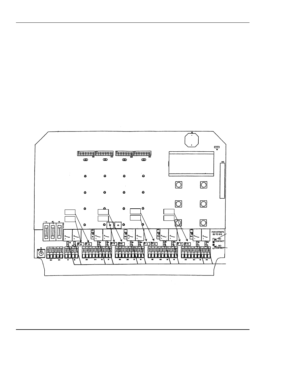
4 outputs, Figure 8: relay jumper and 4-20ma pot location – ENMET MX-42A User Manual
Page 16
ENMET Corporation
MX42A C
ONTROL
12
4.4 Outputs
4.4.1 Relays
With the position of jumpers
S3
through
S12
, the contacts of the relays for each channel can be selected. The
contacts can be either open or closed during the alarm condition. see F
IGURE
8. The factory set position is normally
closed.
This selection is made by moving the corresponding jumper. The standard factory setting, relays (except for the fault
relay) are energized in the non-alarm condition.
4.4.2 4-20 mA Current Output
A 4-20 mA output is available on the terminal block for each channel. It serves to connect the
MX 42A C
ONTROL
to a
chart recorder or to any other data acquisition system (maximum load resistance is 600 ohms).
N
OTE
:
The 4-20 mA output is preset in the factory: 4 mA corresponds to a display of 0 and 20 mA corresponds to a
full-scale value.
Potentiometers P5, P6, P7 and P8 (for channels 1, 2, 3 and 4 respectively) adjust the 4 mA.
Potentiometers P21, P22, P23 and P24 (for channels 1, 2, 3 and 4 respectively) adjust the 20 mA
Figure 8: Relay Jumper and 4-20mA POT Location
Jumpers
S3 to S12
P5
P21
P6
P22
P7
P23
P8
P24
Jumper position
for NC contact
Jumper position
for NO contact