4 connection of the control to external devices, Figure 5: connection to external devices – ENMET MX-42A User Manual
Page 10
ENMET Corporation
MX42A C
ONTROL
6
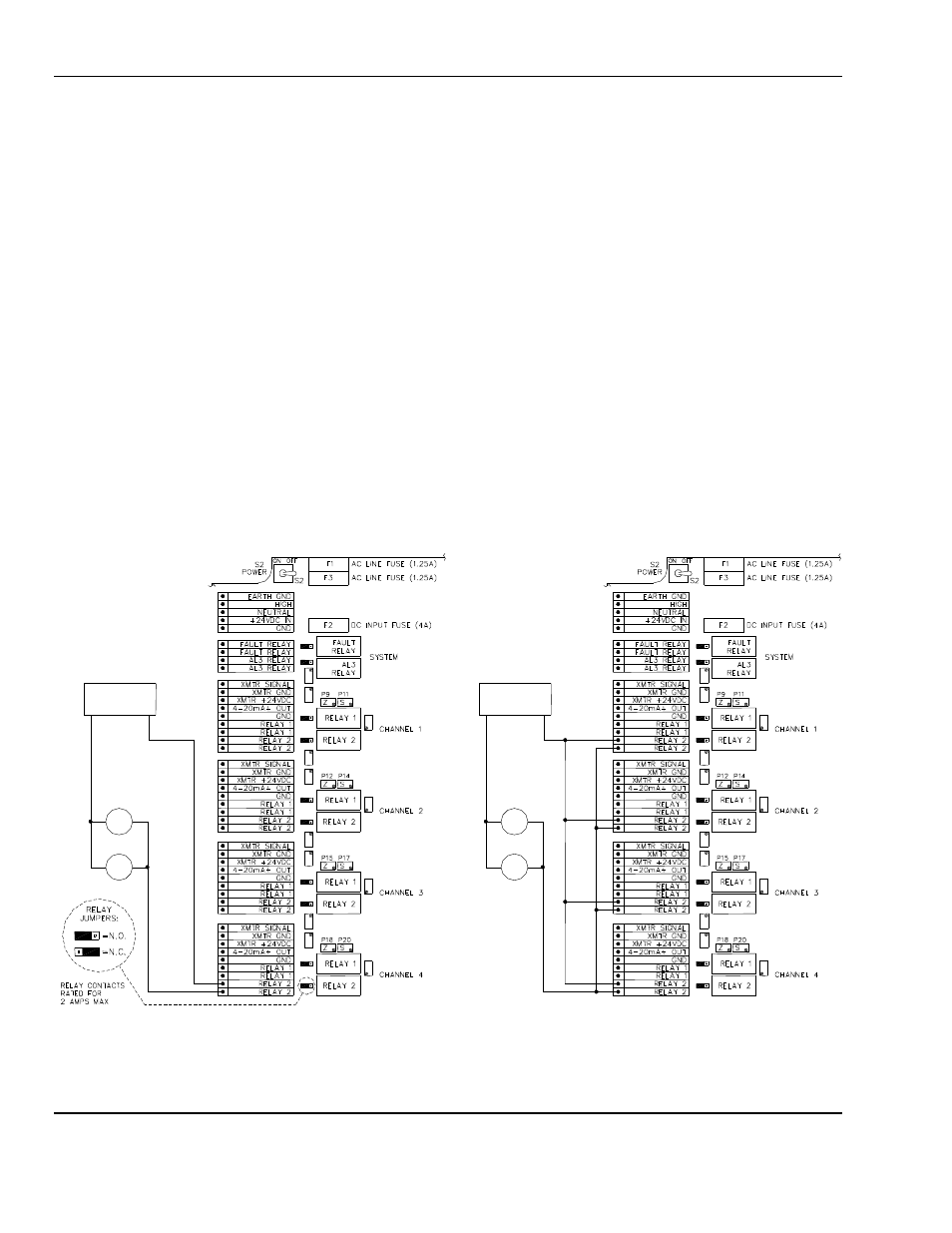
3.4 Connection of the Control to External Devices
Auxiliary alarms should be powered from an independent power source separate form the instrument power to avoid
alarm failure due to controller malfunction.
3.4.1 Connection to Auxiliary Alarms
The
MX 42A C
ONTROL
has 10 relays that can be used to control external devices such as: horns, solenoid valves,
telephone callers, exhaust fans, etc.
The relays are assigned to functions as follows:
For Each Channel:
•
one relay,
RELAY 1
, actuated by alarm 1
•
one relay,
RELAY 2
, actuated by alarm 2
For All Channels:
•
A common relay,
CR RELAY
, actuated by the high alarm of any channel
•
One relay,
FAULT RELAY
, associated with faults detected on any channel such as: detector malfunctions, poor
electrical connections, signal current is 0mA or signal current is greater then 25mA.
An example of a connection is shown in Figure 5
•
Example A: a light and horn, connected to
RELAY 2
of channel 4
•
Example B: a light and horn, connected to
RELAY 2
, of channels 1 – 4
N
OTE
:
Contact rating of the
MX42A
C
ONTROL
relays is 2 A for 85
V
AC
to 240
V
AC
or up to 30
V
DC
. External relays
must be added if the devices to be controlled require higher current requirements.
3.4.2 4-20mA Current Output
For each channel, the
MX 42A C
ONTROL
has a 4-20 mA output which can be used for the transfer of measurements to
a recorder or data logger. In a loop configuration, the maximum resistance is 600 ohms. The 4-20 mA outputs have
common ground connections.
Example A
Example B
Note:
Labeling on board will appear different then shown in this figure.
Figure 5: Connection to External Devices
Power
Source
Power
Source
Light
Light
Horn
Horn