0 maintenance, Unit, Figure 9: potentiometer location – ENMET MX-42A User Manual
Page 17
MX42A C
ONTROL
ENMET Corporation
13
5.0 Maintenance
5.0 Maintenance
5.0 Maintenance
5.0 Maintenance
The
MX 42A
C
ONTROL
requires practically no servicing at all. Nevertheless, since it is a safety device, it is still
necessary to calibrate the detectors periodically.
C
AUTION
:
The procedures and adjustments described in the following sections must be performed by authorized
personal. Failure to follow instructions may jeopardize accurate measurements.
5.1 Adjustment of sensor/transmitter and the MX 42A C
ONTROL
unit
adjustment consists of calibrating the zero of the sensor/transmitter in clean air and the gain of the sensor/transmitter to
the reference gas.
For each channel, set the microswitches as follows
Microswitch 8 = in operation
Microswitch 7 = maintenance
Microswitch 6 = calibration
In the maintenance mode, the Control current output is set to 2 mA.
N
OTE
:
If left in calibration mode, the channel automatically changes over to fault after 30 minutes.
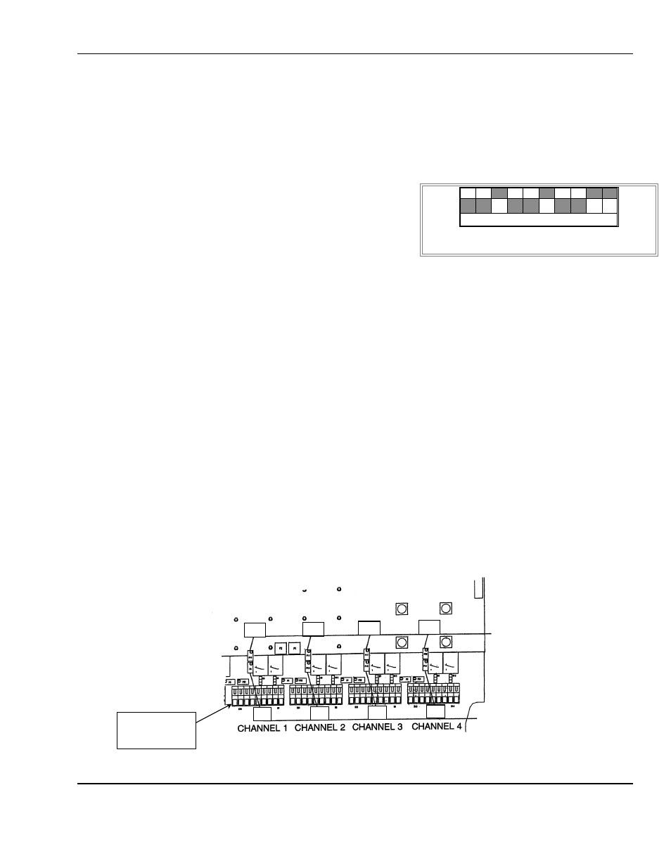
Voltmeter readings are taken at test points of sensor/transmitter refer to S/T manual for location and across
OUTPUT+
, 4-20mA–
terminal for each channel of the
MX42A
C
ONTROL
. See F
IGURE
4, 9.
Adjustment of MX42A C
ONTROL
zero
With the sensor/transmitter in clean air, set the output of the sensor/transmitter to zero (4mA). Then use MX42A
potentiometer: F
IGURE
9, Zero Adjust
P9 for channel 1
P12 for channel 2
P15 for channel 3
P18 for channel 4
to display 0000 on the channel in question. If the ambient air at S/T is not free of contamination, use air from a cylinder.
Adjustment MX42A C
ONTROL
gain
•
Apply the correct calibration gas to the sensor/transmitter, and set the sensor/transmitter output to appropriate output
see S/T manual for proper setting.
•
Adjust the
CONTROL
display to the value of the calibration gas using potentiometer:
F
IGURE
9, Span Adjust
P11 for channel 1
P14 for channel 2
P17 for channel 3
P20 for channel 4
Remove Calibration Gas and return to the microswitch configuration to normal operation:
Microswitch 8 = in operation
Microswitch 7 = normal
Microswitch 6 = calibration
Figure 9: Potentiometer Location
Zero Adjust
POTs
Span Adjust
POTs
1
2
3
4
5
6
7
8
9
10
Example of Microswitch in calibration mode
gray areas indicate position of each switch
P11
P9
P14
P17
P20
P12
P15
P18
Terminal
Cannel 1