0 start-up and operation – ENMET MX-42A User Manual
Page 11
MX42A C
ONTROL
ENMET Corporation
7
4.0 Start-up and Operation
4.0 Start-up and Operation
4.0 Start-up and Operation
4.0 Start-up and Operation
Once the control has been installed and connected, turn it on with the toggle switch,
S2
, located on the inside bottom
left corner.
OFF
is up
ON
is down
When the
MX42A
C
ONTROL
is turned on it initiates a test mode, checking the proper operation of the LEDs, LCD and
the buzzer for about a minute. All alarms are inhibited during this test mode. Then, the
MX 42A C
ONTROL
displays
channel 1 for one minute before starting the normal display cycle of each channel.
2 cases can happen:
a)
If: Channel 1 is in operation
The display indicates
INIT
and then displays the actual measurement value, and the green LED blinks indicating
the channel is in operation, the yellow LED is on steady indicating the channel on display.
b)
If: Channel 1 is off
The display indicates
STOP
, the yellow LED is on steady the channel on display and the green LED is off
indicating the channel is not in operation.
During the normal display cycle of all channels, each channel is scanned by the
MX 42A C
ONTROL
every 9 seconds,
and the measurement is displayed for 3 seconds.
On the front of the control F
IGURE
6, the switches 1, 2, 3 and 4 are used to display the respective channel
measurement for one minute on the display. After one minute, the display returns to normal display cycle.
The
TEST
switch triggers the lighting of all signal lamps, all segments of the LCD display and the functioning of the
buzzer.
The
BUZZER
switch resets the alarms and clears the buzzer alarm.
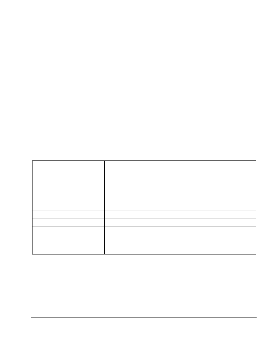
For each channel, there are 5 LEDs to indicate the status of the channel.
LED
Description
Display/Operation
[ Lighting bolt on front panel ]
Paired yellow LED to the left and green LED to the right:
When the green LED is blinking the channel is in test mode.
When the green LED is on steady the channel is in operation.
When the yellow LED is on steady the channel is being displayed.
AL1 [ Bell on front panel ]
Alarm 1 red LED when in alarm
AL2 [ Bell on front panel ]
Alarm 2 red LED when in alarm
AL3 [ Bell on front panel ]
Alarm 3 red LED when in alarm
Fault signal / Calibration signal
[ Wrench on front panel ]
Lower most yellow LED
When the yellow LED is on steady it indicates a malfunction on the line.
When the yellow LED is blinking the channel is in calibration mode.
In case of an alarm or fault, the audio alarm on the control panel latches, to clear press the
BUZZER
switch. The
LEDs will clear when the channel is no longer in alarm condition.
N
OTE
:
The buzzer can be inhibited by moving the jumper on the top right corner of the display board to the
OFF
position. See figure 1 for location of jumper.
C
AUTION
:
There is no visual indication that the buzzer is in inhibited. Return jumper to
ON
position before normal
operation.