ENMET MX-32 User Manual
Page 7
MX32 E
NGUARD
ENMET Corporation
3
2.2 Front panel features
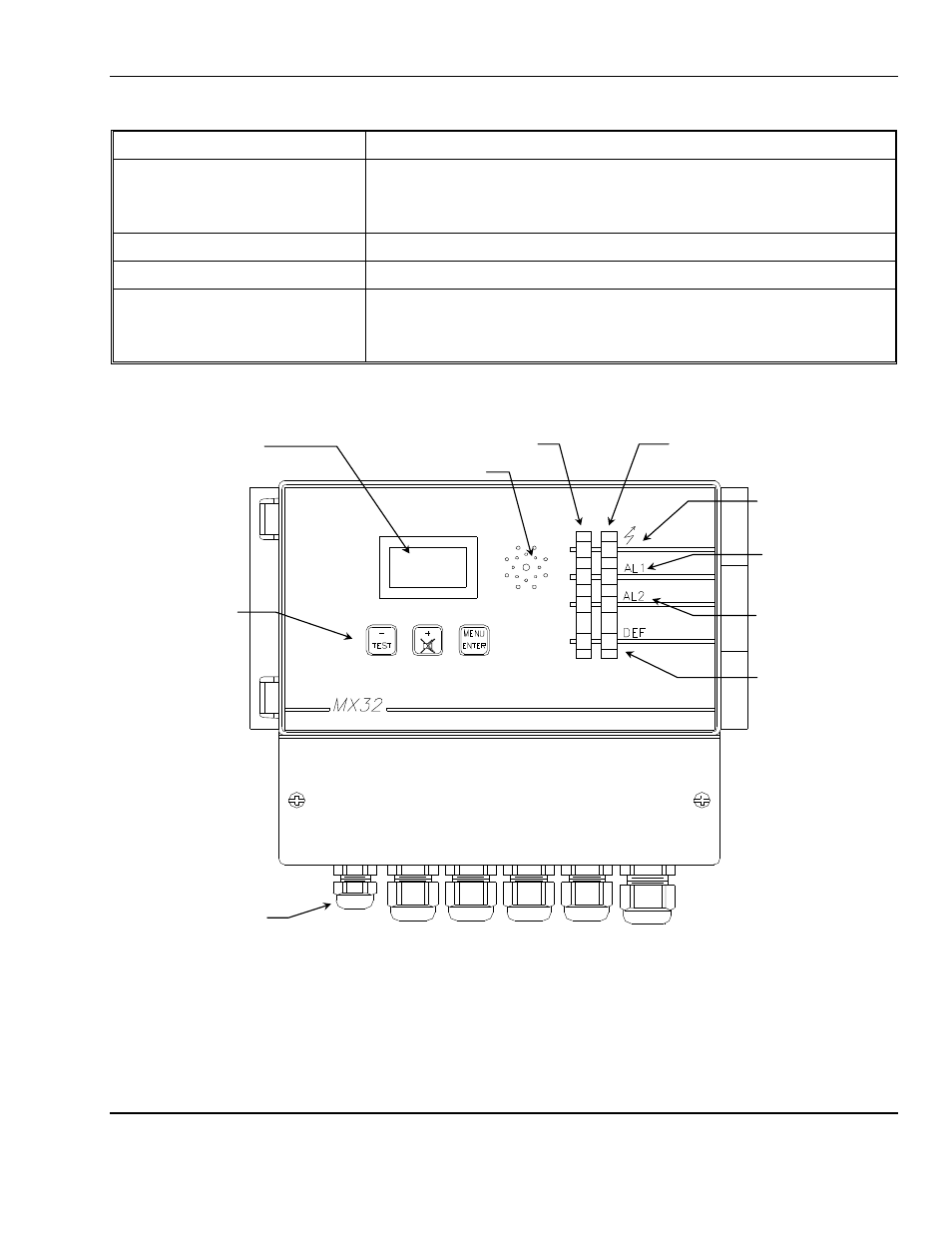
See Figure 2 for location of features.
LED
Description
Display/Operation
[ Lighting bolt on front panel ]
Green LED
When the green LED is blinking the channel is in program mode.
When the green LED is on steady the channel is in operation.
AL1 [ Bell on front panel ]
Alarm 1 red LED when in alarm
AL2 [ Bell on front panel ]
Alarm 2 red LED when in alarm
Fault / Calibration / Program
[ Wrench on front panel]
Lower most yellow LED
When the yellow LED is on steady, it indicates a malfunction on the line.
When the yellow LED is blinking the channel is in calibration or program mode.
Figure 2: MX32 Front Panel
Display LCD
See figure 3 for details
Strain Relief
For input cables
Fault / Calibration /
Program LED for
each channel
Channel 2
LEDs
Channel 1 LEDs
Alarm 2 LED for
each channel
Alarm 1 LED for
each channel
Display / Operation
LED for each channel
Front Panel
Switches
Buzzer