ENMET MX-32 User Manual
Page 10
ENMET Corporation
MX32
E
NGUARD
6
3.2 Wiring the MX32 Control
The electrical installation should conform to appropriate electrical codes, such as the National Electrical Code in the
United States.
W
ARNING
:
The compliance of the installation to appropriate codes is not
ENMET
’s responsibility.
The
MX32 C
ONTROL
should be powered through circuit breakers provided for this purpose.
W
ARNING
:
Continuous gas detection and alarm systems (110
V
AC
/220
V
AC
/ 24
V
DC
/
12
V
DC
powered) become
inoperative upon loss of primary power. Contact factory for specifications and pricing of backup
battery systems.
Each channel of the
MX32 C
ONTROL
has a terminal strip to which all wiring for that channel is connected. A typical
two-channel circuit board is shown in Figure 5 and wiring for this terminal is shown in Table 1.
3.2.1 Relay Contacts
MX32
CONTROL
relay contacts for the first two alarm levels are on the
RL, 1, RL and 2
positions of each channel
terminal strip, as indicated in Figure 5 and Table 1. There are 3-pin headers for setting relays to normally open or
normally closed operation. The location of these headers is indicated in Figure 5. To set the relays, place the jumpers
on the position 2 & 3 pins for NO operation or positions 1 & 2 for NC operation. These jumpers are placed in the NC
operation positions at the factory. See Table 1a. These relays have a maximum capacity of 2 Amp at 230 Volts.
The Fault Relay (DEF), system alarm relay contacts are on the main board, as shown in Figure 5.
Auxiliary alarms should be powered from an independent power source separate form the instrument power to avoid
alarm failure due to controller malfunction.
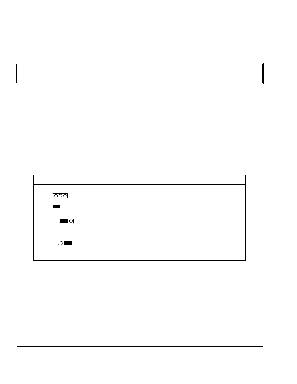
Table 1a: Fault and Alarm Relay Setting
Jumper Position
Relay setting
3-pin header
Pin # 1 2 3
2-pin jumper
3-pin header located near associated relay:
Fault relay (DEF) = J103
Channel 1 – AL1 relay = J105, AL2 relay = J101
Channel 2 – AL1 relay = J108, AL2 relay = J107
See Figure 5 for location of each 3-pin header.
Jumper on pins 1 & 2
Jumper on pins 1 and 2 relay NC operation (no power and alarm condition)
(Factory Setting)
Jumper on pins 2 & 3
Jumper on pins 2 and 3 relay NO operation
3.2.2 Wiring Requirements
Sensor/Transmitters:
Wiring to the Sensor/Transmitters should be by two or three wire shielded cable. The
recommended cable is 18 gauge three wire,
ENMET
part number 66017-006, Alpha-1747C or
equivalent.
Output Loop:
Wiring to output loop should be similar two wire shielded cable.
Relay:
Relay wiring can be suitable insulated wire.