3 internal circuitry of the isa-44-2-od, Pc2 (channel 3), Isb1 – ENMET ISA-44-2OD User Manual
Page 8
ENMET Corporation
ISA-44-2-OD
4
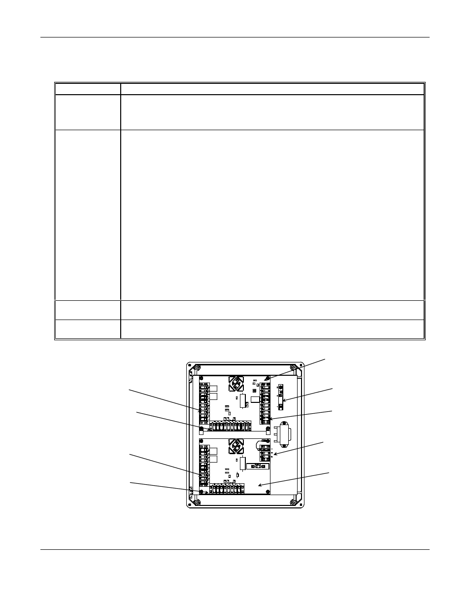
2.3 Internal Circuitry of the ISA-44-2-OD
See Figure 2, 3 and 4 for interior location of ISA-44-2-OD circuit boards, terminal blocks, etc.
Feature
Description
Relay Outputs
For both high and low-level alarms (TB1, TB3, TB4). Relays can activate a remote alarm signal when
either a hazardous gas or oxygen deficiency level is detected or when the
AC
or
DC
power is interrupted.
There are five double-pole relays. These furnish normally open, normally closed, and common terminals.
Relay current is 5 amps, non-inductive surge, 2 amps steady
Potentiometers
The potentiometers (POT) vary critical circuit resistances, which vary the sensor's sensitivity, and are
essential to recalibration procedures. The unit is initially calibrated at the factory.
The potentiometers are described below.
§
Heater Adjust (R1) For adjusting the sensor heater operating voltage (see Section 3.4).
R1 is located on PC1 and PC2.
§
Low Level Alarm Set (R2) For low-level alarm adjustment (recalibration see Section 5.2).
R2 is located on PC1 and PC2.
§
High Level Alarm Set (R3) For high-level alarm adjustment (recalibration; see Section 5.2).
R3 is located on PC1 and PC2.
§
Meter Adjust (R4) To adjust and set the meter for the appropriate gas response (recalibration).
R4 is located on PC1 and PC2.
§
Purge Adjust (R36)
For adjusting the sensor heater purging voltage (toxic gas detection
channel only). Located only on PC1.
§
Oxygen Alarm Adjust (R52) For oxygen alarm adjustment (oxygen cell recalibration; see Section
5.2.2). R52 is located on PC1.
§
Null Adjust, (R44), Full Scale Adjust (R46), Low Level Set (R48) To adjust and set the meter
for the appropriate oxygen response (oxygen cell recalibration). These potentiometers are located on
PC1 only.
Power Terminal
Block (TB6)
Terminal to connect the unit to voltage source. Use the correct watertight fitting for the cord or conduit
when supplying power to unit.
Intrinsic Safety
Barrier (IS1)
To electrically isolate the oxygen cell and prevent the accidental application of high voltage to the cell.
Figure 2: Internal Circuitry Features of the ISA-44-2-OD
PC1
(Channels 1 & 2)
See Figure 3
PC2
(Channel 3)
See Figure 4
ISB1
Intrinsic Safety Barrier
TB6
Power Terminal
TB3
Oxygen Channel
TB1
Channel 1 – Relay
TB4
Channel 3 – Relay
TB5
Channel 3 – Sensor
TB2
Channel 1 – Sensor