ENMET ISA-44-2OD User Manual
Page 13
ISA-44-2-OD
ENMET Corporation
9
3.3 Sensor Hook-up
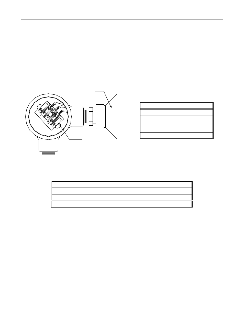
The oxygen cell comes packaged in a sealed vapor proof bag. The cell needs to be installed in the remote sensor
enclosure after the enclosure has been mounted. See Figure 6. This procedure is the same as the procedure described
in Section 5.3
The MOS sensor is connected to the ISA-44-2-OD control unit with three conductor wiring, use the correct oiltight
fitting. Two conductors supply heater current to the sensor. The third conductor is a signal wire. Size of heater wire
depends on the distance between the particular sensor and the control unit. See Table 4.
Sensor wires correspond to the normal wire code:
orange – heater
brown – heater ground
blue – signal
Figure 7: Internal View of Sensor Wiring
N
OTE
: The three color-coded wiring attachments must be performed by the user when replacing the sensor.
Table 4: Recommended Wire Gauge
Distance from Sensor to Control Unit
Recommended Wire Gauge
250 feet
16 AWG
350 feet
14 AWG
Longer Distances
Contact Factory
C
AUTION
: After you mount and install the ISA – 44-2-OD, you must adjust the sensor heater voltage (see Section 3.4).
This equipment is usually permanently installed, with sensor, power, and relay wires run through hard conduit. The
enclosure is not punched, so wiring may approach the enclosure from any direction; however, the bottom of the
enclosure is the best wiring entrance surface.
1.
The
OPERATE
switch should be in the
HORN OFF
position.
2.
Insert each set of sensor wires through a conduit; install with a watertight fitting and tighten the fitting by hand.
Be sure to leave enough wire inside the enclosure for easy hook-up to terminals. The location of terminals
corresponding to each sensor is shown in Figure 3, 4 and 7.
Sensor Wiring
F
OR
812 / 813 / 814 S
ENSORS
Position
Function
Wire Color
1
Signal
(Blue)
2
Heater
(Orange)
3
Ground
(Brown)
Optional
Splash Shield
Sensor Wiring
Terminal