2 sample air supply, 3 power supply, 4 outputs – ENMET PROAIR 2200 User Manual
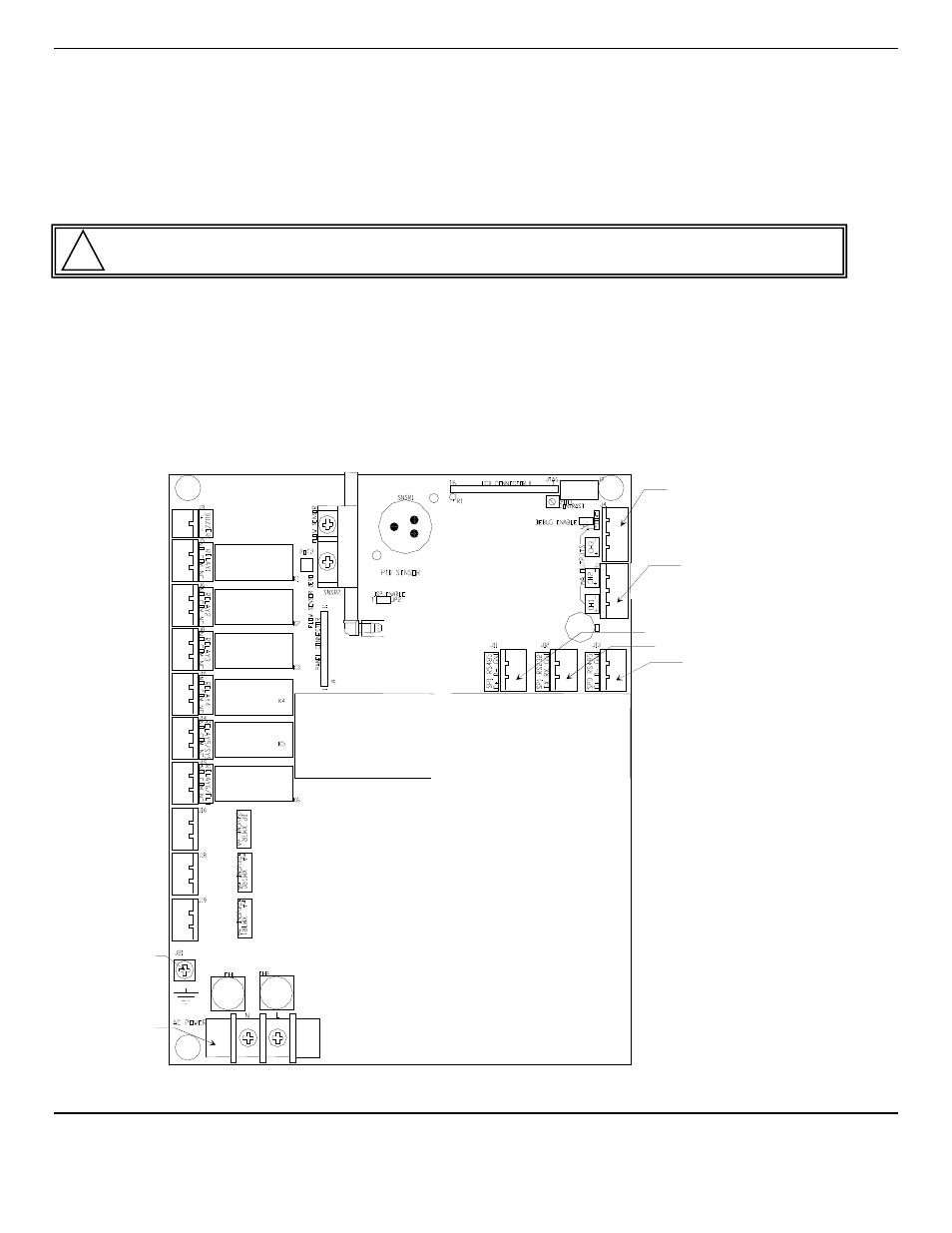
Page 9: Figure 2a: relay, input and output terminals
P
RO
A
IR
2200
ENMET Corporation
6
3.2 Sample Air Supply
Tap the pipe or tank containing the breathing air and use appropriate fittings to connect the sample input hose. The instrument
is designed to operate from an air supply pressure 55
PSIG
.
The sample air exits through the luer fitting(s) located on the bottom of the enclosure. See Figure 1. Take care not to obstruct
this exit port.
3.3 Power Supply
The input power can vary from 100 to 240
V
AC
, 50/60 Hz. Mains power should be connected to the Power Input Terminal
J23
and the ground screw
J21
. Se
e Figure 2 for location.
W
ARNING
:
Continuous gas detection and alarm systems become inoperative upon loss of primary power.
Upon supplying air and power to the instrument:
The green power on LED is lit.
The display backlight is lit, and instrument will step through a start-up sequence: unit serial number, software revision and
gases monitored may be shown on the display.
The instrument may go into alarm briefly, but the sensors stabilize quickly. If the instrument persists in alarm, acknowledge the
alarm by pressing the
AUDIO DEFEAT
/
ALARM ACKNOWLEDGE
switch. If alarm persists longer than 30 minutes, call
ENMET
customer service personnel.
3.4 Outputs
Two types of alarm outputs are available, relay contacts and 4-20mA outputs.
Figure 2A: Relay, Input and Output Terminals
Relay 1
Channel 1
Alarm 1
Relay 2
Channel 2
Alarm 1
Relay 3
Channel 3
Alarm 1
Relay 4
Channel 4
Alarm 1
Relay 5
Channel 1-4
Alarm 2
Relay 6
Ch 1-4 / System
Fault
Connector
Dew Point Sensor
Connector
4-20mA Input
Connector
4-20mA Input
Connector 2
Channel 3 & 4
4-20mA Output
Connector 1
Channel 1 & 2
4-20mA Output
Connector RS485
Connector RS232
Connector RS485
Ground Screw J21
Power Input
Terminal J23
!