0 operation – ENMET PROAIR 2200 User Manual
Page 12
P
RO
A
IR
2200
ENMET Corporation
9
4.0 Operation
4.1 Normal Operation Condition
With the
P
RO
A
IR
2200
installed as described in
Section 3, and in clean air, the
POWER
green LED is on, the display is lit and
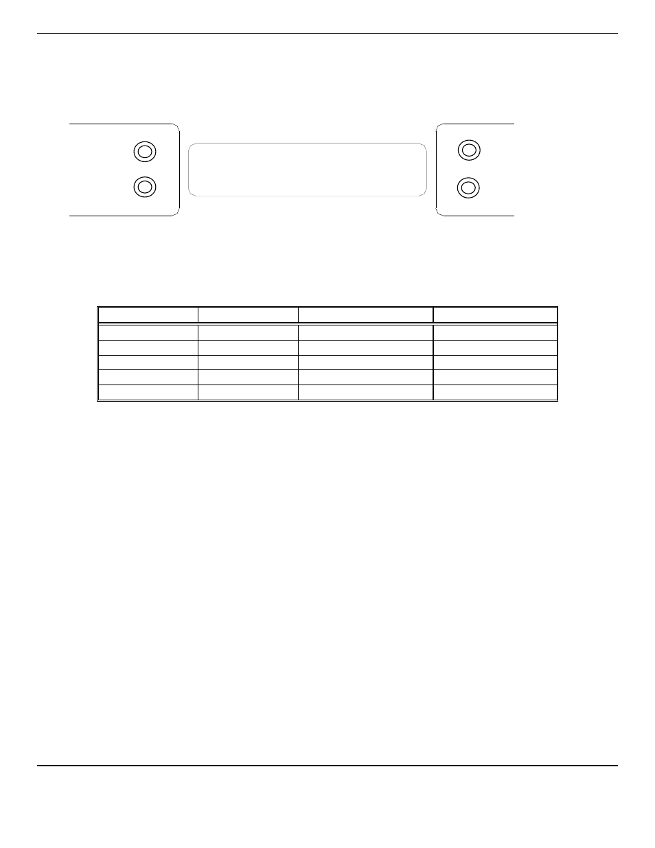
the information on the display is as shown in
Figure 4 Display, for the sensor(s) installed in the
P
RO
A
IR
2200.
The red alarm
and fault LEDs are not lit.
Example of display with CO(ch 1), Dew Point((ch 2), Oxygen(ch 3) and CO
2
(ch 4)options installed
Figure 4: P
RO
A
IR
2200
Operational Display
4.2 Alarm Set Points
There are two alarm set points for each installed channel of the
P
RO
A
IR
2200
. The factory settings of these alarm set points
are shown in
Table 3.
Table 3: Typical Factory Alarm Set Points
Typical Channel #
Gas
Alarm 1, Flashing LED
Alarm 2, Steady LED
1
Carbon Monoxide
10 ppm
20 ppm
2
Dew point
35°Fahrenheit at 55
PSIG
50°Fahrenheit at 55
PSIG
3
Oxygen Deficiency
19.5 % by volume
23.5 % by volume
4
Carbon Dioxide
500 ppm
1000 ppm
4
Hydrocarbon
5 ppm
10 ppm
These alarm set points can be changed within limits; see the maintenance section of this manual for the procedure.
If the CO concentration increases above that of the alarm set point, the associated red LED is lit, the associated relay
changes state, and the audio alarm is activated.
If the dew point increases above that of the alarm set point, the associated red LED is lit, the associated relay changes state,
and the audio alarm is activated.
If the oxygen content of the sample air decreases below the deficiency alarm set point, the associated red LED is lit, the
associated relay changes state, and the audio alarm is activated.
If the oxygen content of the sample air exceeds that of the abundance alarm set point, the associated red LED is lit, the audio
alarm is activated, and both the oxygen alarm relay and the oxygen high alarm relay change state.
The HC sensor can only detect and alarm to hydrocarbons with an Ionization Potential of less then 10.6
eV
. See
Appendix
B.
The HC sensor is broad range in nature and is unable to differentiate between different hydrocarbons.
The Alarm 1 differential value is the delay of the
P
RO
A
IR
2200
staying in alarm condition until after the measured reading
has returned past the alarm point by the differential value.
Example: If the alarm set point is
Λ
10 and the differential is 2,
the
P
RO
A
IR
2200
will go into alarm at 10 and stay in alarm until the reading has dropped below 8.
CO
0
O2 20.9
DP -20
CO2 300
CO
PPM
O
2
%
DEW
POINT
CO
2
PPM