頁面 64, Calibration check, Trace rotation adjustment – Elenco 30MHz Dual Trace User Manual
Page 64
61
MAINTENANCE
2. Set the probe to X10 (compensation adjustment is not possible in the X1 position).
3. Touch tip of probe to CAL terminal.
4. Adjust oscilloscope controls to display 3 or 4 cycles of CAL square wave at 5 or 6
divisions amplitude.
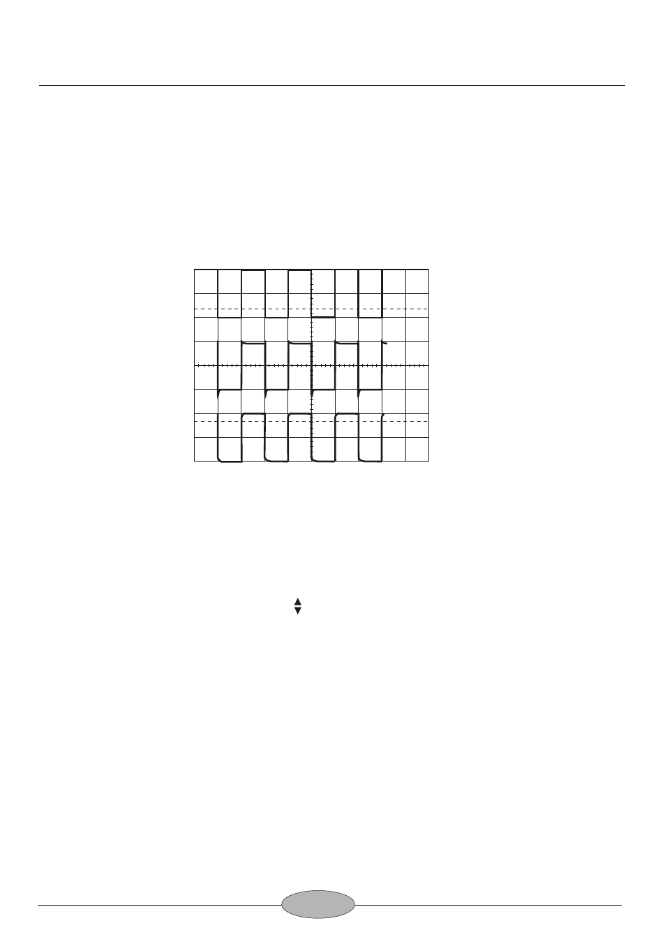
5. Adjust compensation trimmer on probe for optimum square wave (minimum
overshoot, rounding off, and tilt). Refer to Fig.20:
Trace Rotation Adjustment
1. Set oscilloscope controls for a single trace display in CH 1 mode, and with the
channel 1 AC-GND-DC switch set to GND.
2. Use the channel 1 POSITION control to position the trace over the center
horizontal line on the graticule scale. The trace should be exactly with the
horizontal line.
3. Use the TRACE ROTATION adjustment on the front panel to eliminate any trace
tilt.
CALIBRATION CHECK
A general check of calibration accuracy may be made by displaying the output of the
CAL terminal on the screen. This terminal provides a square wave of 2 Vp-p. This
signal should produce displayed waveform amplitude of four divisions at 0.5 V/DIV
sensitivity for both channel 1 and 2 (with probes set for direct). With probes set for
X10, there should be four divisions amplitude at 50 mV/DIV sensitivity. The
VARIABLE controls must be set to CAL during this check.
100
90
10
0
Correct Compensation
Over Compensation
Insufficient Compensation
Fig.20 Probe Compensation Adjustment