頁面 59, Phase difference measurements, Method no.1 – Elenco 30MHz Dual Trace User Manual
Page 59
56
APPLICATION
PHASE DIFFERENCE MEASUREMENTS
Method No.1
(Refer to Fig.15)
This procedure is useful in measuring the phase difference of signals of the same
frequency.
1. Apply the two signals to the CH 1 and CH 2 input jacks, selecting the dual-trace
display mode (either ALT or CHOP).
2. Set the trigger SOURCE switch to the signal witch is leading in phases (or to LINE
if device is line voltage operated) and use VOLTS/DIV controls to adjust the two
waveforms so they are equal in amplitude.
3. Use the Y POSITION control to position the waveforms in the vertical center of the
screen. Use the TIME/DIV and VAR SWEEP controls to adjust the display so one
cycle of the reference signal occupies 8 divisions horizontally (see Fig.
). The
TRIG LEVEL and X POSITION controls are useful in achieving this display. The
display should be as shown in Fig.
, where one division now represents 45 in
phase.
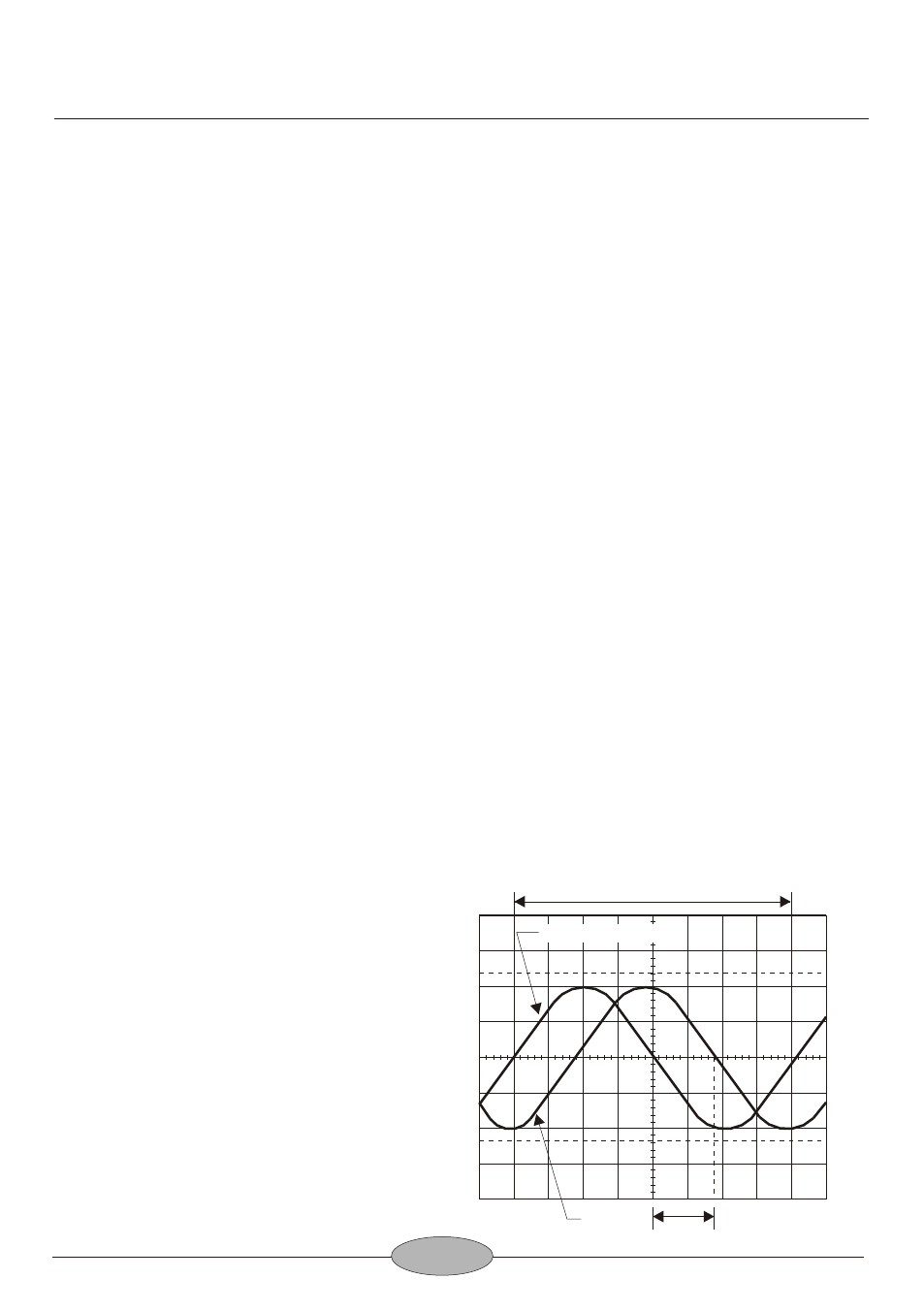
4. Measure the horizontal distance between corresponding points on the two
waveforms. Multiply the distance (in division) time 45 per division to obtain the
phase difference.
The measurement is summarized by the following equation:
Phase difference = Hor div x 45 /div
For the example shown in Fig.15, the horizontal distance is 1.7 divisions. Thus,
the phase difference is calculated as follows:
Phase difference = 1.7 x 45 /div = 76.5
15
15
°
°
°
°
°
Fig.15
Phase Difference Measurement
100
90
10
0
1 cycle
Phase difference
Comparison
signal
Reference Signal