頁面 41 – Elenco 30MHz Dual Trace User Manual
Page 41
27
38
2. Do not obstruct the ventilating holes in the case, as this will increase the scope's
internal temperature.
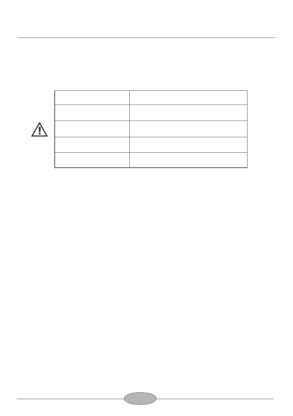
3. Excessive voltage applied to the input jacks may damage the oscilloscope. The
maximum ratings of the inputs are as follows:
4. Always connect a cable from the ground terminal of the oscilloscope to the
chassis of the equipment under test. Without this precaution, the entire current for
the equipment under test may be drawn through the probe clip leads under
certain circumstances. Such conditions could also pose a safety hazard, which
the ground cable will prevent.
5. The probe ground clips are at oscilloscope and earth ground and should be
connected only to the earth ground or isolated common of the equipment under
test. To measure with respect to any point other than the common, use CH 2-CH 1
subtract operation, with the channel 2 probe to the point of measurement and the
channel 1 probe to the point of reference. Use this method even if the reference
point is a dc voltage with no signal.
OPERATING INSTRUCTIONS
Input Terminal
Maximum Allowable Input Voltage
CH1, CH2 Input
400 Vpeak (DC+AC peak)
EXT TRIG Input
300 Vpeak (DC+AC peak)
Probe Input (x10)
600 Vpeak (DC+AC peak)
Z-Modulation Input
30 Vpeak (DC+AC peak)