頁面 52 – Elenco 30MHz Dual Trace User Manual
Page 52
49
APPLICATION
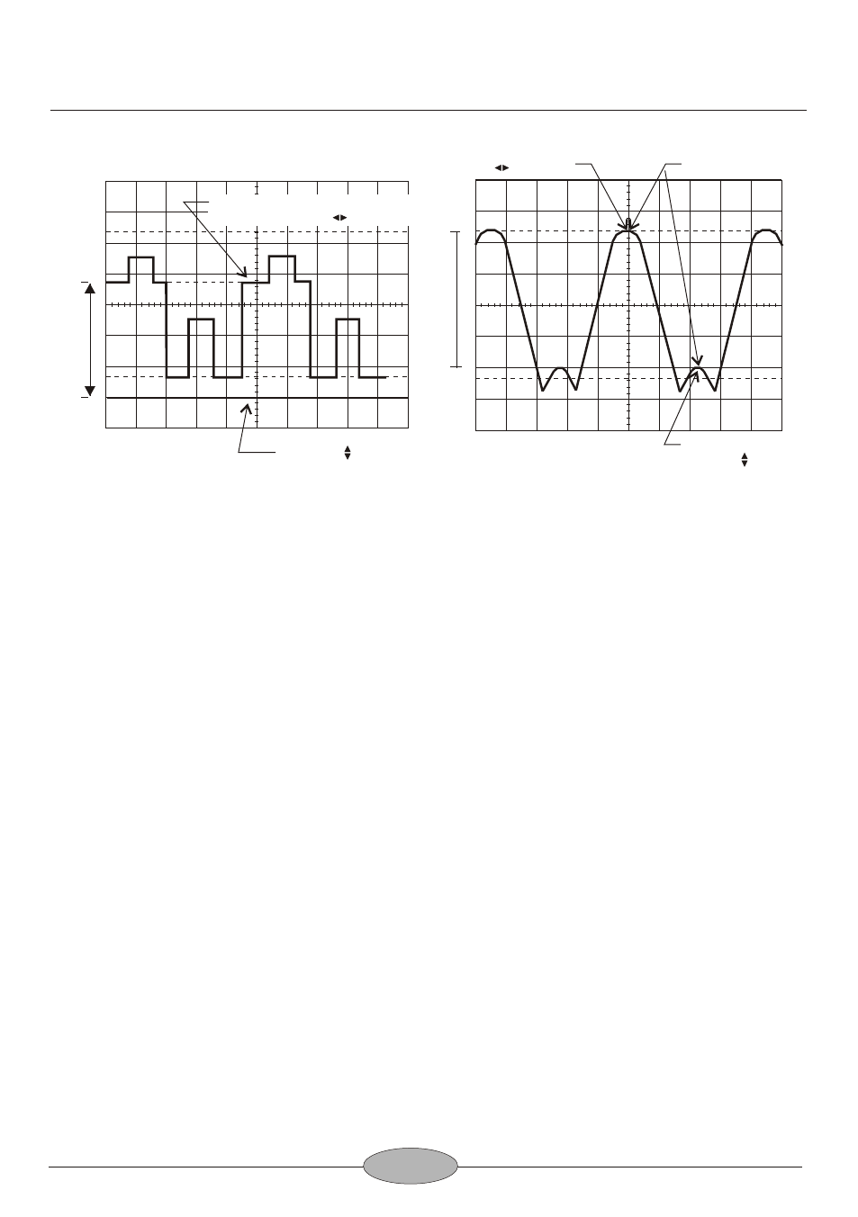
MEASUREMENT OF VOLTAGE BETWEEN TWO POINT
ON A WAVEFORM
(Refer to Fig.8)
This procedure may be used to measure peak-to peak voltages, or for measuring the
voltage difference between any two points on a waveform.
1. Connect the signal to be measured to the input connector, set the CH 1/CH 2
switch to the channel to be used, and set the AC-GND-DC switch to AC. Set the
VOLTS/DIV and sweep TIME/DIV controls to obtain a normal display of the
waveform to be measured. The VARIABLE control must be set to CAL.
2. Using the X POSITION control, adjust the waveform position such that one of the
row points falls on a major horizontal graduation line.
3. Using the X POSITION control, adjust the second point to coincide with the center
vertical graduation line.
4. Measure the vertical distance between the two points( at least 3 divisions
desirable for best accuracy). Multiply the number of divisions by the setting of the
VOLTS/DIV control. If a probe is used, further multiply this by the probe
attenuation ratio.
The measurement is summarized by the following equation:
Voltage = Vert div x VOLTS/DIV x probe
100
90
10
0
Measuring point adjusted to the
center vertical scale by position
Ground potential
adjusted by POSITION
(reference line)
100
90
10
0
Adjust to the center
vertical scale with
POSITION
Points to be measured
Adjust to the horizontal
scale with POSITION
Fig.7 DC Voltage Measurement
Fig.8 Voltage Measurement
V
e
rt
ic
a
l d
is
ta
n
ce
V
e
rt
ic
a
l d
is
ta
n
ce
b
e
tw
e
e
n
tw
o
p
o
in
ts