頁面 57, Pulse rise time and fall time measurements – Elenco 30MHz Dual Trace User Manual
Page 57
54
APPLICATION
PULSE RISE TIME AND FALL TIME MEASUREMENTS
(Refer to Fig.13)
For rise time and fall time measurements, the 10% and 90% amplitude point are
used as starting and ending reference points.
1. Apply a signal to the input jack and set the CH 1/CH 2 switch to the channel to be
used. Use the VOLTS/DIV and VARIABLE controls to adjust the waveform peak
to peak height to six divisions.
2. Using the Y POSITION control, adjust the display so that the waveform is
centered vertically on the display. Set the sweep TIME/DIV control to as fast a
setting as possible while still being able to observe both the 10% and 90% points.
Set the VAR SWEEP control to the CAL position.
3. Use the X POSITION control to adjust the 10% point to coincide with a vertical
graduation line and measure the horizontal distance in divisions between the 10%
and 90% points on the waveform. Multiply this by the sweep TIME/DIV setting and
also by 1/10 if the X10 magnification mode was used.
NOTE:
Be sure that the correct 10% and 90% lines are used. For such measurements the
0, 10, 90 and 100% points are marked on the CRT screen.
The measurement is summarized by the following equation:
Rise Time = Hor div x TIME/DIV (x 1/10 if X10 is used)
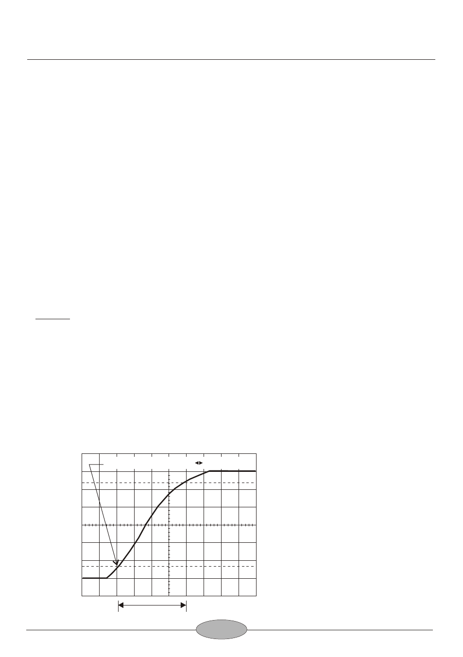
For the example shown in Fig.13, the horizontal distance is 4.0 divisions. The
sweep TIME/DIV setting is 2μ s. The rise time is calculated as follows:
Rise Time = 4.0 (div) x 2 (μs/div) = 8 μs
Fig.13
Rise Time and
Fall Time Measurement
100
90
10
0
Rise time
Adjust to the vertical scale with POSITION