Project 2: and gate, Aq b, Q= ab – Elenco Understanding Logic Gates and Circuits User Manual
Page 9: Ab q
U
1
6
Project 2:
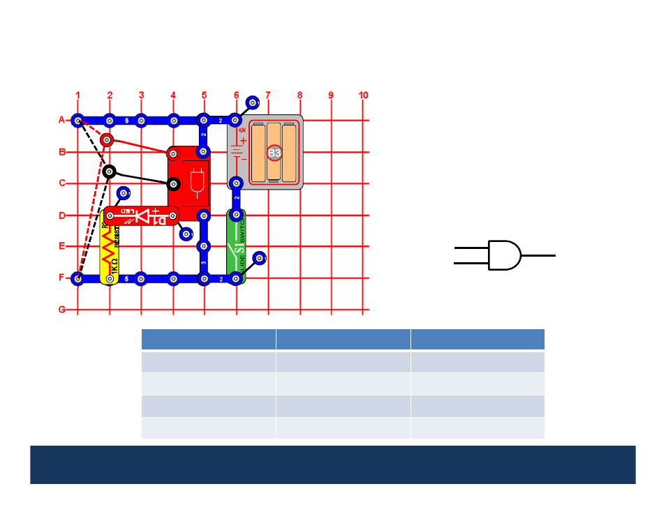
AND Gate
This circuit demonstrates how the AND
Gate (U16) works. Turn the slide switch
(S1) on. Connect the loose ends of the red
and black wires to either low voltage
(denoted as a “0”) or high voltage
(denoted as a “1”). If, and only if, both
input A
AND
input B are high (both 1s),
then the Q output will be high (1), and the
red LED (D1) will be on.
AND gates are used in digital logic circuits to perform a logical multiply. When one of the inputs is low (0),
the output is low (i.e. multiply by 0). The output will only be high (1) when both inputs are high.
A
Q
B
Input (A)
Input (B)
Output (Q)
0
0
0
0
1
0
1
0
0
1
1
1
1
1
1
1
1
2
2
2
2
2
3
3
2
The output of an AND gate is often
represented as the product of the
inputs, so
Q
= AB
.
9
1
0
2
2
1
3
2
A
B
Q
See also other documents in the category Elenco Toys:
- Upgrade Kit SC100 to SC300 (76 pages)
- Snap Circuits Jr.® Educational 100 Exp. (48 pages)
- Upgrade Kit SC300 to SC500 (64 pages)
- Snap Rover ® (24 pages)
- XP&trade (64 pages)
- Snap Circuits LIGHT ® (84 pages)
- Snap Circuits Extreme® Educational 750 Exp. (88 pages)
- Projects PC1-PC73 (60 pages)
- Electronics 202 (132 pages)
- Snaptricity® (92 pages)
- Upgrade Kit SCROV10 to SCROV50 (48 pages)
- Snap Circuits Green ® (80 pages)
- C Adapter for Snap Circuits® (2 pages)
- Motion Detector Kit (20 pages)
- Digital Roulette Kit (16 pages)
- FM Wireless Microphone Kit (12 pages)
- AM Radio Kit (32 pages)
- AM Radio Kit (36 pages)
- AM/FM Radio Kit (64 pages)
- Circuit Maker Skill Builder 125 (64 pages)
- Circuit Maker Sound Plus 200 (80 pages)
- Understanding Logic Gates (16 pages)
- Tumbling Robot (12 pages)
- Solar Energy (16 pages)
- C2D Scope (16 pages)
- 288x Astrolon Telescope with Aluminum Tripod (1 page)
- Simulated Frog Dissection Kit (1 page)
- Talking Galaxy Planetarium with Night Light (1 page)
- Night’n Day® (10 pages)
- Radio Controlled Black Widow (1 page)
- Handheld Microscope (2 pages)
- Water Filtration Kit (8 pages)
- 6-in-1 Solar Kit (18 pages)
- Microscope Set in Carrying Case (1 page)
- Mobile 20 Telescope (1 page)
- Mechanical Drum (20 pages)
- Aerial Screw (20 pages)
- Swing Bridge (20 pages)
- Printing Press (24 pages)
- MultiBarrel Cannon (20 pages)
- Armored Car (24 pages)
- Paddleboat (20 pages)
- SelfPropelled Cart (20 pages)
- Catapult (24 pages)