Introduction, Logic gates – Elenco Understanding Logic Gates and Circuits User Manual
Page 7
Introduction
Logic Gates
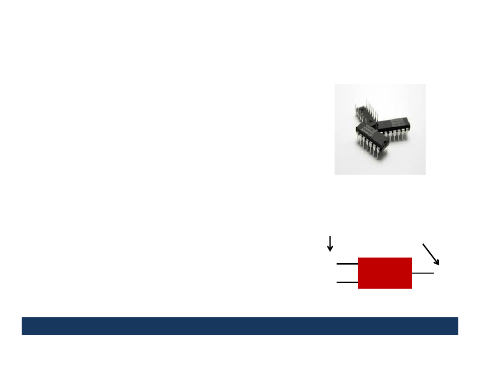
A digital logic gate is an Integrated Circuit (IC) device that
makes logical decisions based on various combinations of
digital signals presented to it’s inputs.
Digital logic gates can have more than one input signal,
but generally have a single output signal, just like the
decision box on the previous slide.
In the following projects, the input digital signals will be
represented by A and/or B and the output digital signal
will be represented by Q.
The next six projects will demonstrate how the output
digital signal is determined by the input digital signals for
various different digital logic gates (NOT gate, AND gate,
OR gate, NAND gate, NOR gate, XOR gate).
The remaining projects will demonstrate the input/output
characteristics of some common combinations of digital
logic gates, called digital logic circuits.
Almost all modern electronics such as computers and cellphones use digital logic circuitry.
Digital Logic
Gate
A
Q
B
Input Digital
Signals
Output Digital
Signal
7