Project 9: s-r nor latch – Elenco Understanding Logic Gates and Circuits User Manual
Page 16
U19
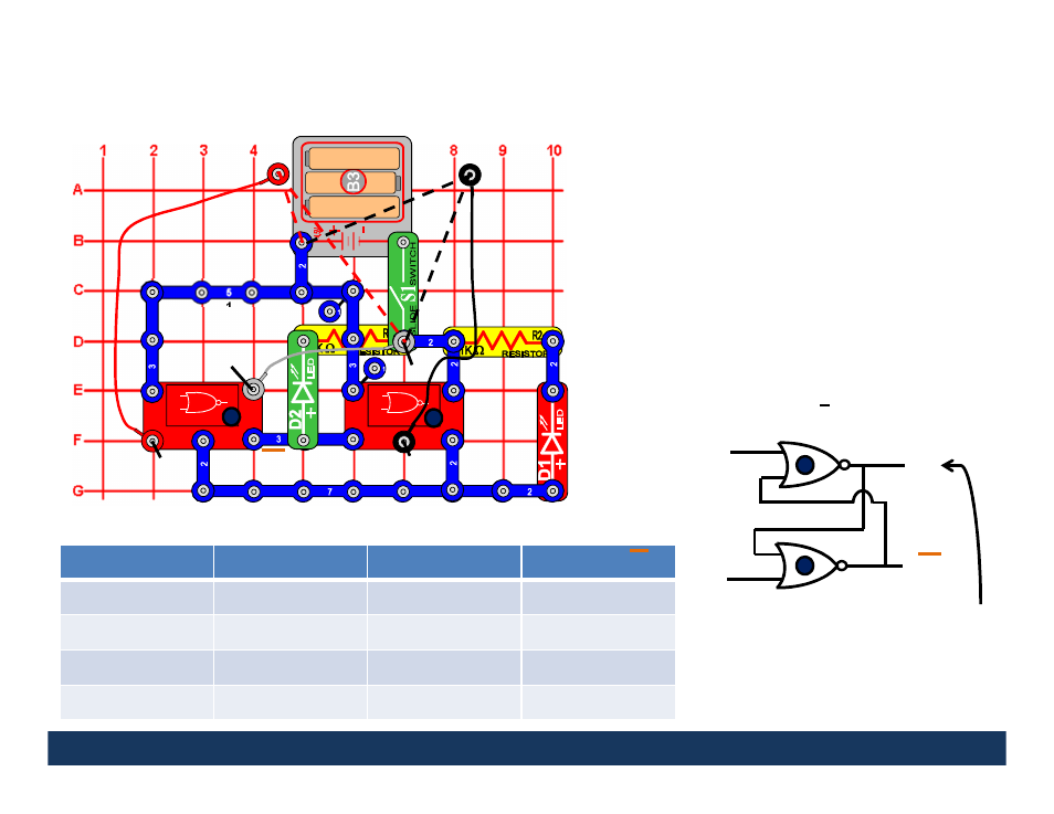
Project 9:
S-R NOR Latch
This circuit demonstrates how the S-R NOR Latch works.
Turn the slide switch (S1) on.
Connect the loose end of
the red wire (S input) to 0 and the loose end of the black
wire (R input) to 1. The red LED will be off (S=0, R=1
resets output Q to 0). Now disconnect the black wire
from 1 and connect it to 0. The red LED remains off (S=0,
R=0 holds the last output state). Now disconnect the red
wire from 0 and connect it to 1. The red LED will be on
(S=1, R=0 sets the output to 1). Now disconnect the red
wire from 1 and connect it to 0. The red LED remains on
(S=0, R=0 holds the last output state).
S=R=1 is the
forbidden state, can you explain why? The green LED
should always be the opposite of the red LED (green LED
off when red LED on and green LED on when red LED off)
since the green LED represents Q which is the opposite
of Q.
S-R NOR Latches can be used to eliminate bouncing in switches.
1
1
1
1
1
1
2
2
2
2
2
U19
2
2
3
2
2
2
R
Q
S
Q
Stays the same when S=R=0
Reset to 0 when S=0 & R=1
Set to 1 when S=1 & R=0
S=R=1 is forbidden
Input (S)
Input (R)
Output (Q)
Output (Q)
0
0
Hold State
Hold State
1
0
1
0
0
1
0
1
1
1
Not Allowed
Not Allowed
R
S
2
2
2
3
16
1
1
2
2
1
0
3
1
1
Q
Q
2
4