Project 1: not gate (inverter), Aq input (a) output (q) 0 1 1 0, Q= a – Elenco Understanding Logic Gates and Circuits User Manual
Page 8
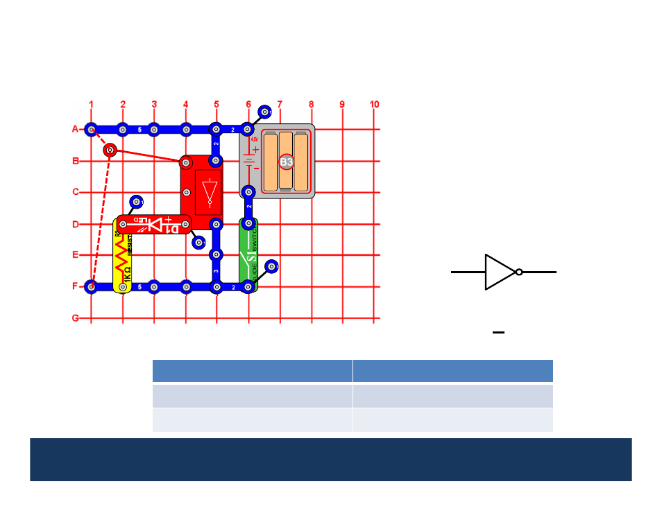
Project 1:
NOT Gate (Inverter)
A
Q
Input (A)
Output (Q)
0
1
1
0
U
1
5
This circuit demonstrates how the NOT
Gate (U15) works. Turn the slide switch
(S1) on. Connect the loose end of the
red wire to either low voltage (denoted
as a “0”) or high voltage (denoted as
“1”). If input A is low (0), then the Q
output will be high (1), and the red LED
(D1) will be on. If input A is high (1),
then the Q output will be low (0) and
the red LED will be off.
1
0
NOT gates are used in digital logic circuits to “invert a voltage level”. A high voltage level (1)
into the NOT gate becomes a low voltage level (0) at the output and vice versa.
1
1
1
1
1
2
2
2
2
2
3
3
The inversion of a state is often
represented
with
a
bar
over
the
variable, so
Q
= A
.
8
1
2
3
2
2
A
Q
See also other documents in the category Elenco Toys:
- Upgrade Kit SC100 to SC300 (76 pages)
- Snap Circuits Jr.® Educational 100 Exp. (48 pages)
- Upgrade Kit SC300 to SC500 (64 pages)
- Snap Rover ® (24 pages)
- XP&trade (64 pages)
- Snap Circuits LIGHT ® (84 pages)
- Snap Circuits Extreme® Educational 750 Exp. (88 pages)
- Projects PC1-PC73 (60 pages)
- Electronics 202 (132 pages)
- Snaptricity® (92 pages)
- Upgrade Kit SCROV10 to SCROV50 (48 pages)
- Snap Circuits Green ® (80 pages)
- C Adapter for Snap Circuits® (2 pages)
- Motion Detector Kit (20 pages)
- Digital Roulette Kit (16 pages)
- FM Wireless Microphone Kit (12 pages)
- AM Radio Kit (32 pages)
- AM Radio Kit (36 pages)
- AM/FM Radio Kit (64 pages)
- Circuit Maker Skill Builder 125 (64 pages)
- Circuit Maker Sound Plus 200 (80 pages)
- Understanding Logic Gates (16 pages)
- Tumbling Robot (12 pages)
- Solar Energy (16 pages)
- C2D Scope (16 pages)
- 288x Astrolon Telescope with Aluminum Tripod (1 page)
- Simulated Frog Dissection Kit (1 page)
- Talking Galaxy Planetarium with Night Light (1 page)
- Night’n Day® (10 pages)
- Radio Controlled Black Widow (1 page)
- Handheld Microscope (2 pages)
- Water Filtration Kit (8 pages)
- 6-in-1 Solar Kit (18 pages)
- Microscope Set in Carrying Case (1 page)
- Mobile 20 Telescope (1 page)
- Mechanical Drum (20 pages)
- Aerial Screw (20 pages)
- Swing Bridge (20 pages)
- Printing Press (24 pages)
- MultiBarrel Cannon (20 pages)
- Armored Car (24 pages)
- Paddleboat (20 pages)
- SelfPropelled Cart (20 pages)
- Catapult (24 pages)