Project 15: half adder, As b c – Elenco Understanding Logic Gates and Circuits User Manual
Page 25
U16
U20
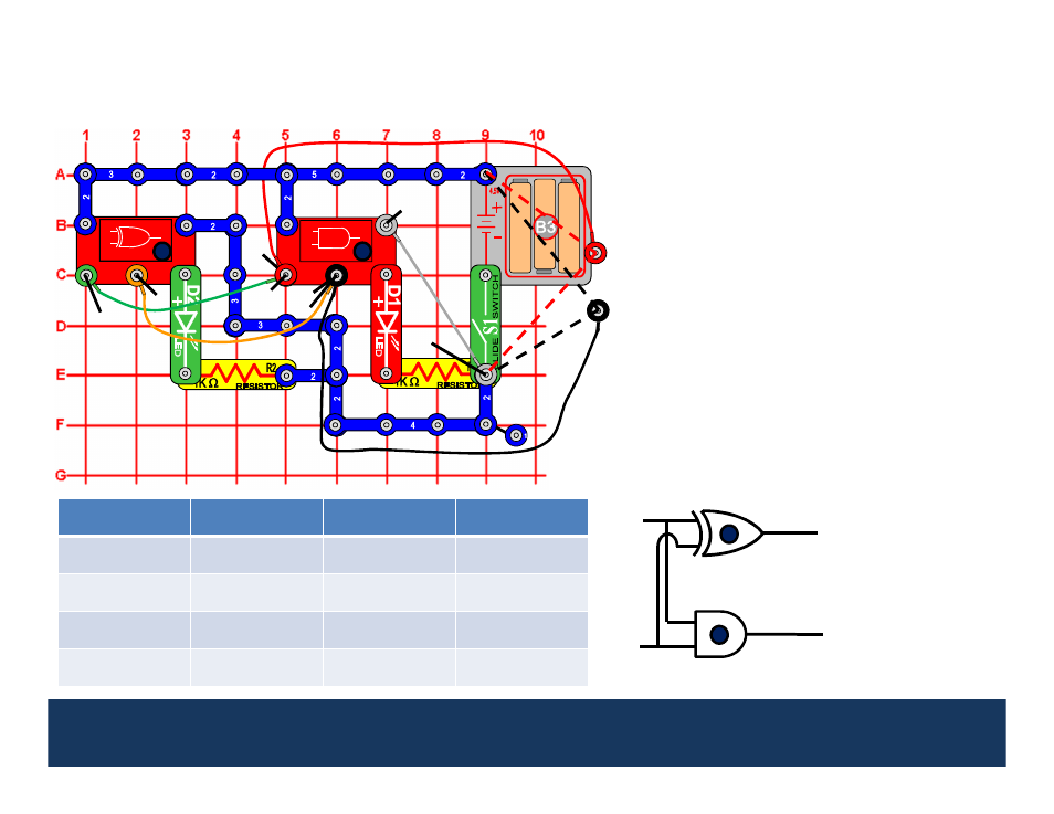
Project 15:
Half Adder
This circuit demonstrates how a half adder
works.
Turn the slide switch (S1) on. The
green LED represents the Sum (S) and the red
LED represents the Carry (C). When the loose
ends of the red and black wires are both
connected to 0 (0+0), both LEDs are off
(S=C=0). When one of the loose ends of the
red and black wires are connected to different
inputs (one to 0 and the other to 1), the green
LED is on and the red LED is off (S=1, C=0).
When the loose ends of the red and black
wires are both connected to 1 (1+1), the green
LED is off and the red LED is on (S=0, C=1)
indicating an overflow condition.
Adders are used in computers and processors as arithmetic logic units,
as well as to calculate addresses, table indices, etc..
1
1
2
1
1
1
2
1
2
2
2
1
2
2
3
2
2
1
1
2
2
2
3
Input (A)
Input (B)
Output (S)
Output (C)
0
0
0
0
0
1
1
0
1
0
1
0
1
1
0
1
A
S
B
C
Represents the
Sum
Represents the
Carry
A
B
4
2
25
1
2
3
3
2
2
S
C
1
2
1
2
1
0
- Upgrade Kit SC100 to SC300 (76 pages)
- Snap Circuits Jr.® Educational 100 Exp. (48 pages)
- Upgrade Kit SC300 to SC500 (64 pages)
- Snap Rover ® (24 pages)
- XP&trade (64 pages)
- Snap Circuits LIGHT ® (84 pages)
- Snap Circuits Extreme® Educational 750 Exp. (88 pages)
- Projects PC1-PC73 (60 pages)
- Electronics 202 (132 pages)
- Snaptricity® (92 pages)
- Upgrade Kit SCROV10 to SCROV50 (48 pages)
- Snap Circuits Green ® (80 pages)
- C Adapter for Snap Circuits® (2 pages)
- Motion Detector Kit (20 pages)
- Digital Roulette Kit (16 pages)
- FM Wireless Microphone Kit (12 pages)
- AM Radio Kit (32 pages)
- AM Radio Kit (36 pages)
- AM/FM Radio Kit (64 pages)
- Circuit Maker Skill Builder 125 (64 pages)
- Circuit Maker Sound Plus 200 (80 pages)
- Understanding Logic Gates (16 pages)
- Tumbling Robot (12 pages)
- Solar Energy (16 pages)
- C2D Scope (16 pages)
- 288x Astrolon Telescope with Aluminum Tripod (1 page)
- Simulated Frog Dissection Kit (1 page)
- Talking Galaxy Planetarium with Night Light (1 page)
- Night’n Day® (10 pages)
- Radio Controlled Black Widow (1 page)
- Handheld Microscope (2 pages)
- Water Filtration Kit (8 pages)
- 6-in-1 Solar Kit (18 pages)
- Microscope Set in Carrying Case (1 page)
- Mobile 20 Telescope (1 page)
- Mechanical Drum (20 pages)
- Aerial Screw (20 pages)
- Swing Bridge (20 pages)
- Printing Press (24 pages)
- MultiBarrel Cannon (20 pages)
- Armored Car (24 pages)
- Paddleboat (20 pages)
- SelfPropelled Cart (20 pages)
- Catapult (24 pages)