Project 14: comparator – Elenco Understanding Logic Gates and Circuits User Manual
Page 23
U19
U15
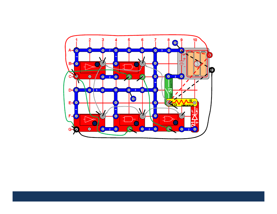
Project 14:
Comparator
Details of the Comparator Block Diagram and Logic Chart on Next Page.
This circuit demonstrates how a comparator works. Turn the slide switch (S1) on. When the loose ends
of the red and black wires are connected to the same input (either 1 or 0), the red LED will be on
(indicating the inputs are the same). When the loose ends of the red and black wires are connected to
different inputs (one to 1 and the other to 0), the red LED is off (indicating the inputs are different).
Can you think of a much simpler circuit than the one above that achieves the same result (hint: it can
be done with just 2 gates)?
U16
1
U15
U16
1
1
1
1
1
1
1
2
2
2
2
2
2
2
2
2
2
2
3
3
3
2
3
3
1
1
2
2
2
2
2
2
3
2
2
2
3
2
3
A
B
2
3
23
1
0
1
5
3
4
1
2
2
Q
See also other documents in the category Elenco Toys:
- Upgrade Kit SC100 to SC300 (76 pages)
- Snap Circuits Jr.® Educational 100 Exp. (48 pages)
- Upgrade Kit SC300 to SC500 (64 pages)
- Snap Rover ® (24 pages)
- XP&trade (64 pages)
- Snap Circuits LIGHT ® (84 pages)
- Snap Circuits Extreme® Educational 750 Exp. (88 pages)
- Projects PC1-PC73 (60 pages)
- Electronics 202 (132 pages)
- Snaptricity® (92 pages)
- Upgrade Kit SCROV10 to SCROV50 (48 pages)
- Snap Circuits Green ® (80 pages)
- C Adapter for Snap Circuits® (2 pages)
- Motion Detector Kit (20 pages)
- Digital Roulette Kit (16 pages)
- FM Wireless Microphone Kit (12 pages)
- AM Radio Kit (32 pages)
- AM Radio Kit (36 pages)
- AM/FM Radio Kit (64 pages)
- Circuit Maker Skill Builder 125 (64 pages)
- Circuit Maker Sound Plus 200 (80 pages)
- Understanding Logic Gates (16 pages)
- Tumbling Robot (12 pages)
- Solar Energy (16 pages)
- C2D Scope (16 pages)
- 288x Astrolon Telescope with Aluminum Tripod (1 page)
- Simulated Frog Dissection Kit (1 page)
- Talking Galaxy Planetarium with Night Light (1 page)
- Night’n Day® (10 pages)
- Radio Controlled Black Widow (1 page)
- Handheld Microscope (2 pages)
- Water Filtration Kit (8 pages)
- 6-in-1 Solar Kit (18 pages)
- Microscope Set in Carrying Case (1 page)
- Mobile 20 Telescope (1 page)
- Mechanical Drum (20 pages)
- Aerial Screw (20 pages)
- Swing Bridge (20 pages)
- Printing Press (24 pages)
- MultiBarrel Cannon (20 pages)
- Armored Car (24 pages)
- Paddleboat (20 pages)
- SelfPropelled Cart (20 pages)
- Catapult (24 pages)