2 > connection standard – Austin Hughes MCS User Manual
Page 4
UM-CV-751-MCS-Q114V1 www.austin-hughes.com
1)
Computer to LCD display connection standard
- Conducts bi-directional communication using serial RS232.
- Use three signal wires of TxD, ( pin 2 ), RxD ( pin 3 ) and GND ( pin 5 ), among the RS232
standard wires, as Fig. 2-1.
- Use DTR ( pin 4 ), RTS ( pin 7 ) for hot-plug detect.
- The distance between the PC computer to LCD display is limited 15 feet.
2)
LCD display to LCD display connection standard
- Conducts bi-directional communication using CAN bus
- A maximum of 64 LCD display units can be daisy chained to one CAN bus, up to 1,000 meters.
- The distance between LCD Displays is limited 300 meters via Cat 5/ 6 cable.
3) Command
communications
The CAN bus requires the MCS module of LCD display registration by sending command < 0x01 >
to add or remove the LCD display(s) from the CAN bus before command communications. Please
refer to page 6 for more details.
All communications are conducted in the form of hexadecimal number, and the checksum calculation
method as below :
Total =
Command + ID + Val1 + Val2 + Val3 + Val4 + Val5 + Val6;
Checksum =
256 – Total;
* Unsigned character of Checksum, Total=0;
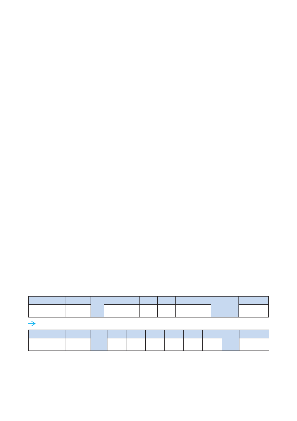
Get Power Status
( e.g. Power ON & ID=1 )
Here, each set functions according to the commands received and responds with ACK at the same time.
Therefore, the operation of each set should be checked after this process.
Header
Command
ID
Val 1
Val 2
Val 3
Val 4
Val 5
Val 6
Checksum
Footer
0x4D,
0x43,0x06
0x04
Power
0x00
0x00
0x00
0x00
0x00
0x0D, 0x0A
Header
Command
0x01
Val 1
Val 2
Val 3
Val 4
Val 5
Val 6
0xFA
Footer
0x4D,
0x43,0x06
0x04
0x01
0x00
0x00
0x00
0x00
0x00
0x0D, 0x0A
< 1.2 > Connection Standard
P.2