1 > connection < part 1 > interface – Austin Hughes MCS User Manual
Page 3
UM-CV-751-MCS-Q114V1 www.austin-hughes.com
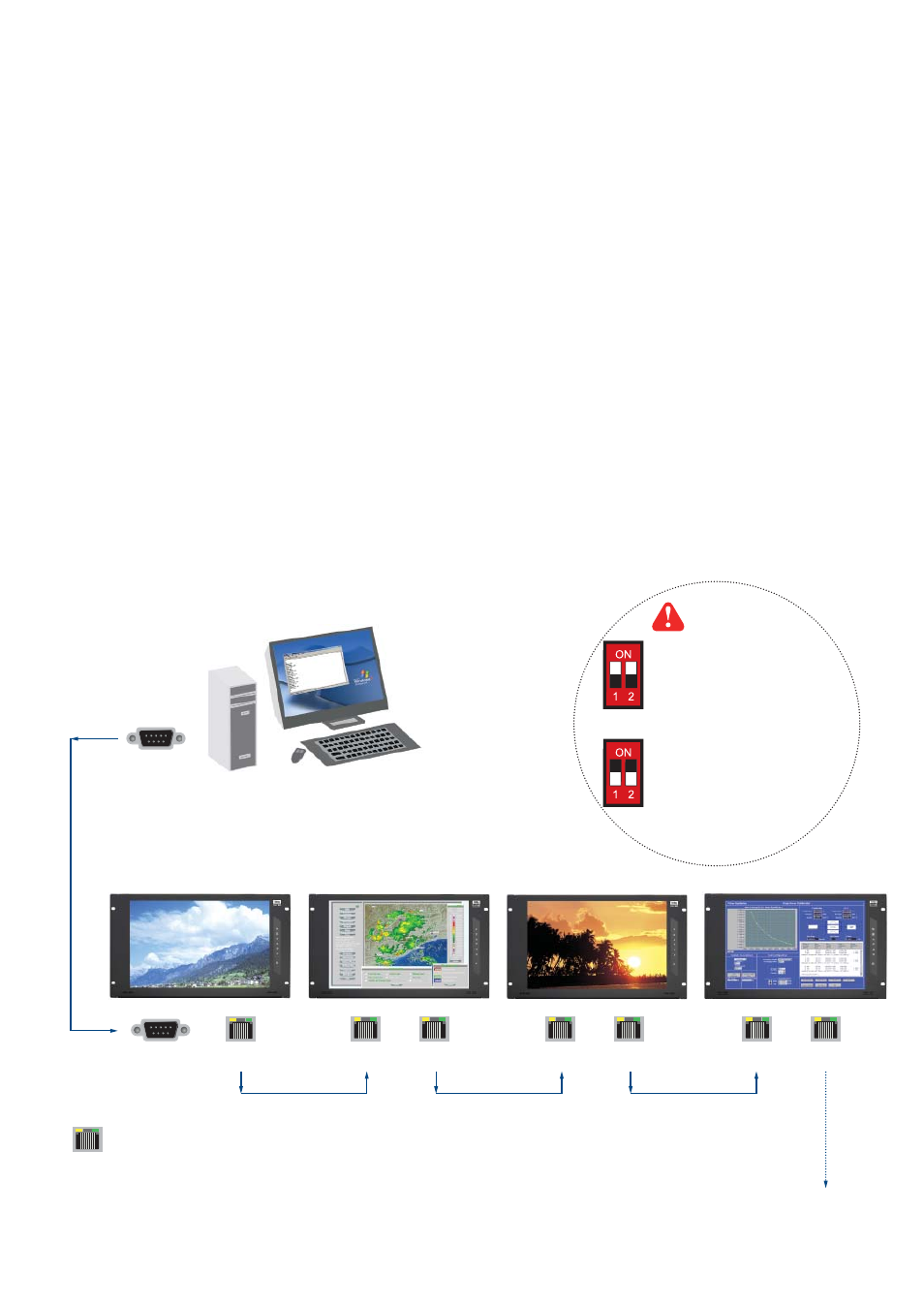
For the 1st and last display,
push the set switch upward
Set switch
For other daisy chain displays,
push the set switch downward
LINK
OUT
IN
OUT
RS-232C
Cat5 / 6 cable
max. 300 meters
up to 64 displays
Daisy chain up to 1,000
meters and 64 displays
RJ-45 jack
IN
OUT
IN
OUT
Cat5 / 6 cable
max. 300 meters
Cat5 / 6 cable
max. 300 meters
15 feet serial cable
( over 15 feet, extender required )
- As shown in Fig. 1-1, fi rst, connect the personal computer’s RS-232C serial port to the 1st LCD dis
play’s LINK port and then begin to add connections from a LCD display, starting from the OUT port.
-
The
fi rst & last LCD displays located at both ends of daisy chain connection must be terminated by
setting the pin 1 & 2 of DIP switch ( Set ) to ON position, located next to OUT port. For other daisy
chain LCD display(s), please keep the pin 1 & 2 of DIP switch at OFF position ( Pin 1 & 2 are
default at OFF position ).
*The new DIP switch setting requires a power cycle of LCD display to take effect.
- The MCS module of LCD display will automatically assign an available ID number from 1 to 64 to
each LCD display when connected to the daisy chain, to eliminate LCD displays trying to use the
same IDs simultaneously.
Fig. 1-1 Connecting the PC & LCD Displays
< 1.1 > Connection
< Part 1 > Interface
P.1