ADLINK Hurricane-QM57 User Manual
Page 44
TME-EPIC-HURQM-R2V9 Revision
2.9
Page 38 of 74
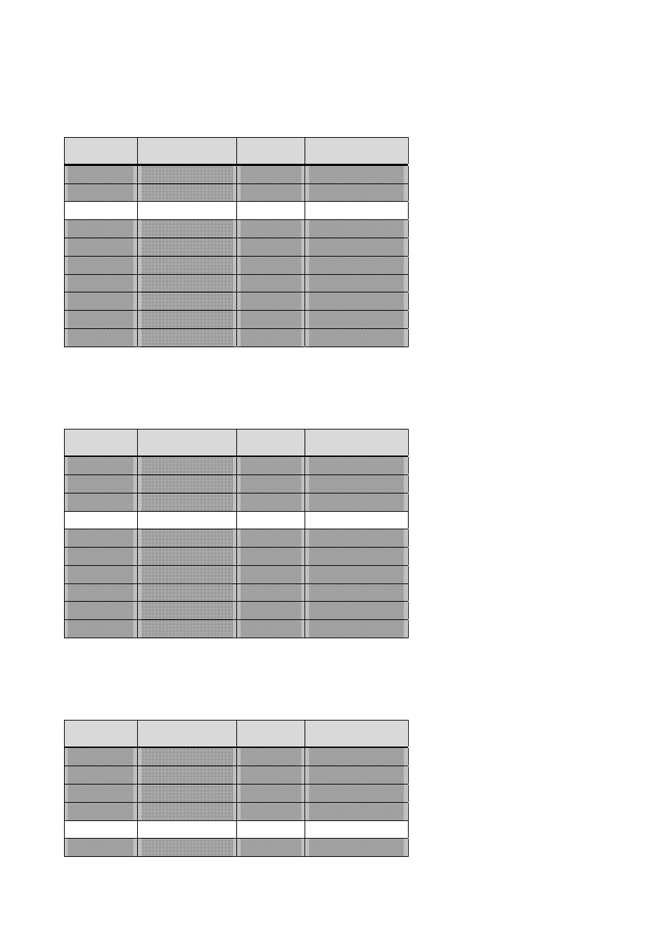
Reset-Button
To reset the board, the signal “Reset-Button” must be pulled to GND.
Pin
Signal
Pin
Signal
1
SMB_CLK
2
SMB_DATA
3
Power Button
4
GND
5
Reset Button
6
GND
7
HDD LED
8
+3.3V (LED)
9
Watchdog
10
+3.3V (LED)
11
Power LED
12
+3.3V (LED)
13
GPIO 64
14
GPIO 65
15
GPIO 66
16
GPIO 67
17
GPIO 1
18
GPIO 6
19
GPIO 7
20
GPIO 28
HDD-LED
To signal HDD activity in your casing connect an external LED from pin 8 to pin 7. The “+3.3V (LED)” supply pin
already incorporates a 330 Ω series resistor.
Pin
Signal
Pin
Signal
1
SMB_CLK
2
SMB_DATA
3
Power Button
4
GND
5
Reset Button
6
GND
7
HDD LED
8
+3.3V (LED)
9
Watchdog
10
+3.3V (LED)
11
Power LED
12
+3.3V (LED)
13
GPIO 64
14
GPIO 65
15
GPIO 66
16
GPIO 67
17
GPIO 1
18
GPIO 6
19
GPIO 7
20
GPIO 28
Watchdog
An external LED signalling that the watchdog has reset the board can be connected from pin 10 to pin 9. The
“+3.3V (LED)” supply pin already incorporates a 330 Ω series resistor.
Pin
Signal
Pin
Signal
1
SMB_CLK
2
SMB_DATA
3
Power Button
4
GND
5
Reset Button
6
GND
7
HDD LED
8
+3.3V (LED)
9
Watchdog
10
+3.3V (LED)
11
Power LED
12
+3.3V (LED)